
Author | Hu Tu Zhen
Source | Automotive Electronics and Software
In modern automotive electronic control systems, the Electronic Control Unit (ECU) plays the role of the “brain”, responsible for controlling key components such as the engine, motor, and battery management system. To enable the same platform model to adapt to different configurations, driving modes, and cope with complex operating environments, the ECU must possess high flexibility and adjustability. ECU calibration is the core technical means to achieve this goal. This article will systematically introduce automotive ECU calibration technology from multiple aspects, including the basic concepts of calibration, hardware and software foundations, implementation methods, protocols, and tools.
01. Basic Concepts of Calibration
1.1 Why is Calibration Necessary?
The fundamental purpose of calibration is to adjust the internal parameters of the ECU so that the vehicle can achieve optimal performance under different configurations, driving modes, and environments. Specifically, the necessity of calibration is reflected in the following aspects:
-
Differentiated Configuration: The same model can achieve functional switch control (e.g., intelligent driving assistance) through calibration, thus forming high, medium, and low configuration versions.
-
Driving Mode Switching: By adjusting different parameter sets of the same function through calibration, various driving modes such as economy, normal, and sport can be realized.
-
Environmental Adaptability: The automotive operating environment is complex and variable (temperature, altitude, slope, etc.), requiring extensive experimental calibration to maintain stable performance in different environments.
-
Compensation for Insufficient Models: Many components (e.g., engines, motors) have characteristics that are difficult to accurately describe through pure mathematical models, necessitating experimental calibration to obtain actual parameters.
-
Production Consistency Assurance: Even the same model of components has manufacturing tolerances, and ECU calibration can compensate for these small differences to ensure consistency in vehicle performance.
Therefore, calibration is not only a means of product differentiation but also a key engineering link to ensure vehicle safety, economy, and driving quality.
1.2 What is Calibration?
Calibration can be likened to the “seasoning” process in cooking: finding the most suitable parameter values through continuous experimentation.
In the ECU, calibration refers to repeatedly adjusting its internal parameters (calibration quantities) according to the performance requirements of the controller or the entire vehicle until the optimal state is reached.
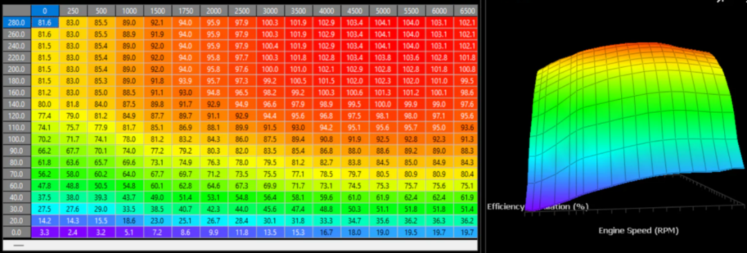
For example, the relationship between engine speed and engine efficiency can be expressed as:
EngEff = a * EngSpeed + b
By calibration, the best values of a and b are found, allowing the vehicle’s response to meet design expectations. Calibration quantities can be a single constant or in the form of arrays or lookup tables. The result of calibration is a set of parameters “hardened” in the ECU, enabling the vehicle to perform optimally under specific conditions.
Source: https://dialedinmotorsports.net/products/standalone-ecu-remote-calibration-live
From a technical perspective, calibration is a system engineering process that involves:
-
Parameter Identification: Determining which parameters need to be calibrated
-
Parameter Optimization: Finding the optimal parameter values
-
Parameter Validation: Confirming the effectiveness of parameters under actual conditions
-
Parameter Hardening: Writing the optimized parameters into the ECU’s non-volatile memory
To better understand this process, we will start with the hardware and software foundations of the ECU for a detailed exploration:
02. ECU Hardware and Software Foundations
To achieve efficient calibration, the storage and access architecture of the ECU must be designed collaboratively from both hardware and software perspectives.
The ECU’s memory is divided into two types: RAM and ROM. RAM, or Random Access Memory, loses data when power is off and is used for runtime data storage; ROM, or Read-Only Memory, retains data when power is off and includes FLASH and EEPROM, used for storing program code, data, and calibration quantities.
Source: https://blog.csdn.net/YPFree/article/details/132551124
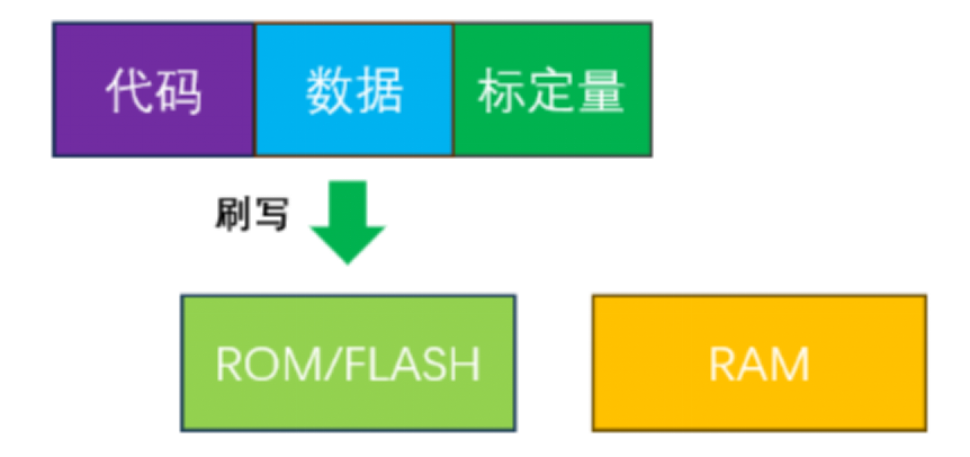
ECU software consists of three parts: program code (Code), data (Data), and calibration quantities (Calibration Data).
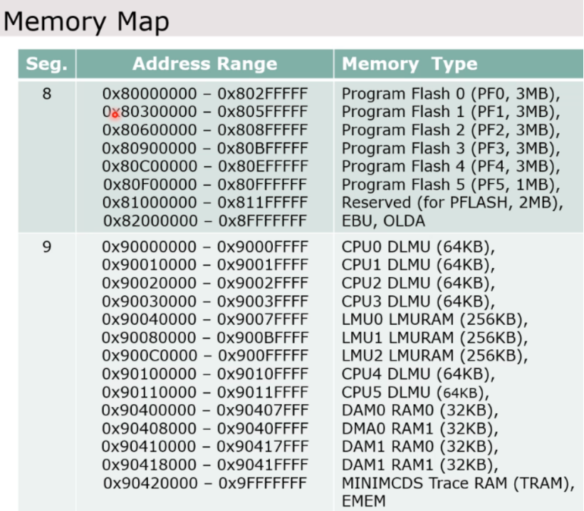
After the software is flashed to the ECU, it is all stored in the corresponding address segment of FLASH, with the underlying principle being that during the compilation and linking phase, the memory mapping technology clarifies the storage locations of each segment. For example, using #pragma directive to specify the storage area for calibration quantities, the linker file defines the specific allocation strategy for FLASH, such as allocating fixed-size storage space for program code, data, and calibration quantities.
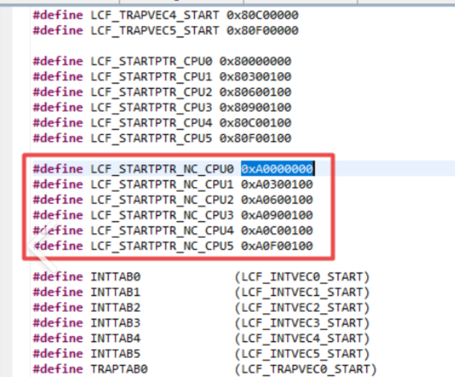
Source: https://blog.csdn.net/qq_20848757/article/details/90542909
During runtime, the program code is still executed in FLASH, while data (including calibration quantities) is copied to RAM, allowing the CPU to read data from RAM to ensure operational efficiency.
Source: https://mp.weixin.qq.com/s/UPhDXRH_P8T3_WUyEd1jWg
In other words, calibration parameters are stored in FLASH as their initial values, while in RAM, they are modifiable runtime values. During system initialization, the startup code copies the calibration parameters from FLASH to the corresponding positions in RAM, ensuring that the ECU starts running from a known state. During online calibration, calibration tools access and modify the parameter values in RAM via bus protocols (such as XCP) to achieve real-time tuning. After tuning is completed, the modified parameter values in RAM must be written back to FLASH through a dedicated programming process to achieve parameter hardening, ensuring that the system continues to operate with optimized parameter states after the next power-up.
03. Storage and Access of Calibration Quantities
Calibration quantities are stored in FLASH as constants and are specified for their storage segments through compilation directives (such as #pragma), with the compiler allocating RAM addresses for them and storing initial values in FLASH.
At startup, the Boot program copies the calibration quantity values from FLASH to RAM.
During runtime, calibration tools (such as INCA, CANape) communicate with the ECU via the XCP protocol to read and write calibration quantities in RAM. There are two common modes:
-
WP (Writable Page) mode: Allows modification of values in RAM.
-
RP (Read-only Page) mode: Only allows reading of initial values in FLASH.
To simplify address mapping, manufacturers such as Infineon and NXP provide an Overlay mechanism, allowing calibration tools to directly access FLASH addresses while actually operating on RAM content.
In the conventional memory access mode, the CPU accesses the Flash memory controller (FMC) through the system bus (AXBS) to perform read and write operations on FLASH memory. This path is the standard way for the ECU to obtain program instructions and fixed data during operation, ensuring the basic operational functionality of the system.
However, the Overlay mechanism changes this access path through hardware remapping technology. When the Overlay function is enabled, the storage access requests issued by the CPU are redirected to the SRC (Switch & Reset Controller) module after passing through the FMC, ultimately accessing SRAM instead of FLASH. This path switch is implemented at the hardware level, is transparent to the CPU, and does not require software intervention.

Source: https://blog.csdn.net/null_scl/article/details/143744421
It is worth noting that although the physical access target has changed, the address signals issued by the CPU still point to the original FLASH address space. The key to the Overlay mechanism is address remapping, which automatically maps the FLASH addresses issued by the CPU to pre-configured SRAM areas. This design allows calibration tools to continue using FLASH addresses for access while actually operating on copies in SRAM, greatly simplifying the calibration process.
After calibration is completed, the modified values in RAM must be written to FLASH, with two common methods:
-
XCP-based flashing: Directly writing to FLASH through the XCP programming instruction set (Overlay must be disabled). This method is efficient but requires the ECU to support XCP programming functionality.
-
UDS-based flashing: Exporting calibration data as a Hex file and flashing it to FLASH via UDS services. This method is highly versatile but has a more complex process.
During the flashing process, attention must be paid to: data verification before flashing, power-off protection during flashing, and data verification after flashing.
04. Calibration Protocols and Tools
In the field of automotive electronic calibration, the XCP protocol and A2L files form the technical foundation of the calibration system. XCP (Universal Measurement and Calibration Protocol), as a standard protocol established by the ASAM organization, provides a unified communication framework for ECU measurement and calibration.
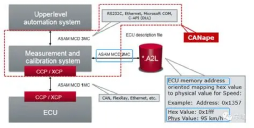
Source: https://developer.aliyun.com/article/1135191
This protocol adopts a master-slave architecture, achieving efficient read and write operations on calibration quantities by defining clear command sets and data structures.
4.1 XCP Protocol
The core advantage of the XCP protocol lies in its transport layer independence design. It supports various underlying communication media, including CAN, Ethernet, FlexRay, etc., making it adaptable to different in-vehicle network architectures. On the CAN bus, XCP typically uses 8-byte data frames for transmission, distinguishing commands and data through identifiers; while on Ethernet, it employs the UDP/IP protocol stack, significantly increasing data transmission rates. This flexibility allows XCP to meet the evolving demands from traditional in-vehicle networks to next-generation Ethernet architectures.
The functionality of the protocol mainly relies on three mechanisms: Data Acquisition (DAQ), Stimulation (STIM), and Calibration (CAL). The DAQ mechanism supports both periodic and event-triggered data acquisition modes, efficiently transmitting measurement data in the form of Data Transfer Objects (DTO) packets. The STIM mechanism allows the master device to send stimulation signals to the slave device for functional testing and validation. The CAL mechanism provides complete calibration functionality, including reading and writing calibration quantities, page switching, and programming control.
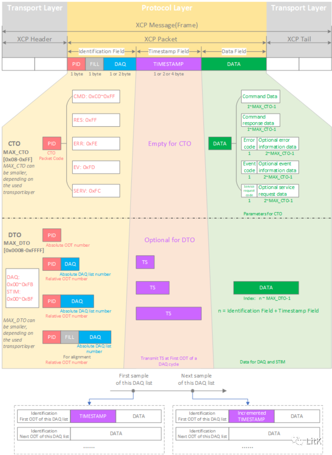
Source: https://blog.csdn.net/FitKi/article/details/129531843
4.2 A2L Files
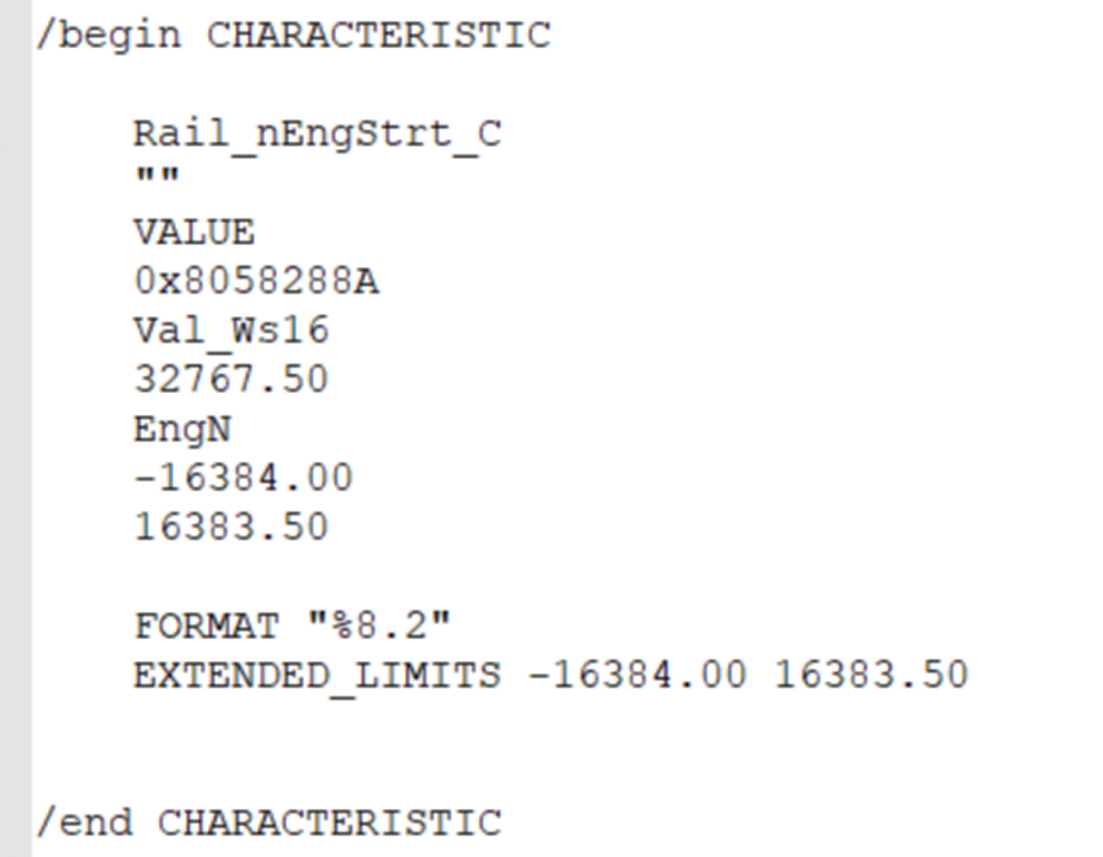
A2L files serve as the “metadata description files” for the ECU, adopting the ASAM-MCD-2MC standard format, providing calibration tools with a complete blueprint for accessing internal ECU information. The file adopts a modular structure and contains the following key information modules:
The header module (HEADER) contains basic project information, version number, and file generation date; the module definition module (MODULE) describes ECU software module information; the measurement definition module (MEASUREMENT) details the name, address, data type, conversion formula, and physical units of each observable quantity; the characteristic definition module (CHARACTERISTIC) includes all attribute information of calibration quantities, such as storage address, data type, conversion rules, and value ranges.
Source: https://zhuanlan.zhihu.com/p/672554410
The generation process of A2L files is usually closely integrated with the software development process. In model-based development, calibration quantity information is automatically extracted from the model using code generation tools; in traditional C code development, it is generated using the MAP file produced by the compiler and related parsing tools. Modern development environments typically implement automated generation of A2L files, ensuring strict synchronization with software versions to avoid human errors.
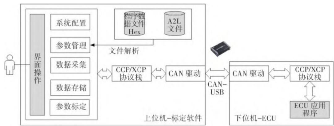
In practical calibration work, commonly used calibration tools form a complete ecosystem. ETAS’s INCA, as a representative of traditional calibration tools, provides powerful functionality and rich plugin support, particularly suitable for the complex calibration needs of large vehicle enterprises. Vector’s CANape is renowned for its user-friendly interface and excellent performance, widely used in research and testing fields. These tools typically support project management, capable of saving the complete state of calibration projects, including parameter settings, measurement configurations, and experimental data, facilitating subsequent data analysis and traceability.
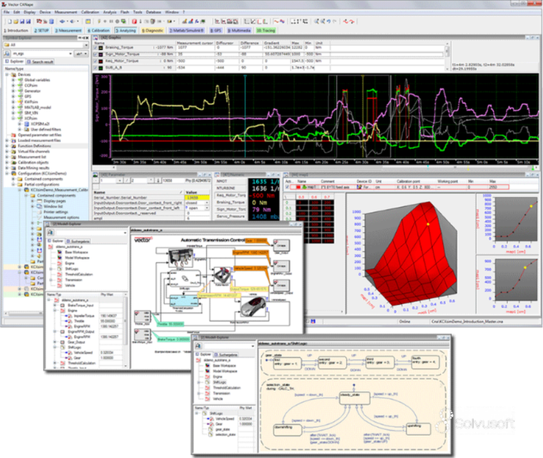
Source: atlantafigures.org/en/ljcupxfl.html
The workflow of calibration tools typically includes the following stages: first establishing a communication connection with the ECU, parsing the internal data structure of the ECU through the A2L file; then configuring measurement tasks, setting the signals to be observed and the sampling period; next, performing online calibration, modifying parameter values in RAM in real-time and observing system responses; finally, using programming functions to harden the optimized parameters into FLASH. The entire process requires strict data verification and version management to ensure the accuracy and traceability of calibration data.
With the development of technology, modern calibration tools have also integrated data analysis functions, capable of real-time processing and visual display of collected data, helping engineers quickly discover patterns and issues. Some advanced tools even support automated calibration, executing calibration processes through script programming, significantly improving calibration efficiency.
05. Systematic Calibration Workflow
Calibration work is a system engineering process that requires adherence to a strict workflow.
Source: https://blog.csdn.net/xcy2014117129/article/details/129357661
A complete calibration cycle typically includes five stages: requirement analysis, scheme design, implementation of calibration, verification testing, and result hardening.
-
In the requirement analysis stage, calibration engineers need to work closely with system engineers and software engineers to clarify performance goals and constraints. This stage requires the preparation of a detailed calibration requirement specification, defining the target value range, accuracy requirements, and testing conditions for each calibration quantity. It also requires the formulation of calibration strategies, determining the calibration order and optimization methods, considering the coupling relationships between parameters.
-
The scheme design stage requires the establishment of the calibration environment, including hardware preparation and software configuration. Hardware aspects include the preparation of calibration equipment, measurement instruments, and experimental vehicles; software aspects include A2L file verification, calibration tool configuration, and test case development. This stage also requires designing data acquisition schemes, determining the signals to be monitored and the sampling frequency, ensuring a comprehensive reflection of system status.
-
The implementation of calibration stage is the core link of online operations, where engineers connect to the ECU using calibration tools and adjust parameters according to predetermined strategies. This process follows the “observe-adjust-verify” cycle: first observing the system performance under current parameters, then cautiously adjusting parameter values, and finally verifying the adjustment effects and recording data. Important calibration operations include basic calibration, functional calibration, and optimization calibration. Basic calibration ensures the basic functionality of the system; functional calibration optimizes performance under specific conditions; optimization calibration involves fine-tuning based on the previous two.
-
The verification testing stage is a comprehensive examination of calibration results, including bench testing, road testing, and environmental adaptability testing. Bench testing verifies basic functionality in a laboratory environment; road testing verifies comprehensive performance in actual usage scenarios; environmental adaptability testing verifies system reliability under extreme conditions such as high cold, high temperature, and high altitude. Each testing stage requires detailed data recording and the preparation of test reports.
-
The result hardening stage is the process of formally applying the optimized parameters to mass production models. This stage requires completing parameter reviews, document preparation, and software release. All calibration data must be included in the configuration management system to ensure version traceability. Additionally, relevant technical documents must be updated, including calibration data manuals, user instructions, and maintenance guides.
06. Conclusion
ECU calibration is a key link in automotive electronic development, connecting control system design, software development, and vehicle validation. Through calibration, the same hardware platform can derive different configurations and styles of vehicles, adapting to diverse market demands. As automotive electronic architecture evolves towards centralization, calibration technology is also advancing towards cloud calibration and automated calibration, but its core—optimizing performance through parameter tuning—remains unchanged.
This article systematically introduces the concepts, implementation methods, protocols, and tools of calibration based on the hardware and software foundations of the ECU, hoping to provide automotive electronic engineers with a clear technical context and practical reference.