Development of ECU Application Layer Model: Data Dictionary and <span><span>Simulink.Signal</span></span> introduces the core object of the data dictionary (<span><span>.sldd</span></span>) in Model-Based Design (MBD), focusing on another core object, <span><span>Simulink.Parameter</span></span>.
<code><span><span>Simulink.Parameter</span></span> is a core object class defined by the Simulink environment, playing a crucial role in the data dictionary throughout the lifecycle of model design, simulation, parameter management, and final product-level code generation. Understanding its essence, purpose, usage, and its relationship with code generation is essential for developing high-quality, maintainable, and industry-standard embedded software.<span><span>Without further ado, let's get to the point:</span></span>
1. <span><span>Simulink.Parameter</span></span> Object
1.1 Definition and Essence
Simulink.Parameter is essentially a metadata container or parameter object, which encapsulates the following key information in a unified entity:
-
Value: The actual value of the parameter (e.g., scalar
<span><span>10.5</span></span>, vector<span><span>[1, 2, 3]</span></span>, matrix, etc.). -
DataType: Precisely specifies the data type of the parameter (e.g.,
<span><span>uint8</span></span>,<span><span>int16</span></span>,<span><span>boolean</span></span>, or custom fixed-point type<span><span>fixdt(1,16,8)</span></span>, etc.). -
Storage Class: Defines how the parameter should be represented and stored in the generated embedded C code.
-
Other Attributes: Includes minimum value (
<span><span>Min</span></span>), maximum value (<span><span>Max</span></span>), unit (<span><span>Unit</span></span>), description (<span><span>Description</span></span>), complexity (<span><span>Complexity</span></span>), and dimensions (<span><span>Dimensions</span></span>), etc.
In short, <span><span>Simulink.Parameter</span></span> is a strongly typed parameter entity with rich attributes and code generation intent declarations, which replaces the practice of directly using raw numerical values within the model or MATLAB base workspace, achieving centralized and standardized management of parameters. This means that parameters scattered across various corners of the model (such as gain values in Gain blocks, breakpoint data in Lookup Tables, constants in Stateflow, etc.) are defined centrally in the data dictionary, and modifying a parameter only requires updating it once in the data dictionary to take effect globally.
By enforcing the specification of attributes such as <span><span>DataType</span></span>, <span><span>Min</span></span>, <span><span>Max</span></span>, etc., in the object definition, it can prevent unexpected data type conversions or value out-of-bounds errors when using the same parameter in different locations in the model; and by using the <span><span>Storage Class</span></span> attribute, it explicitly specifies how the parameter is stored and accessed in the target embedded system. For example:
-
Parameters declared as
<span><span>Const</span></span>or<span><span>AUTOSAR.Constant</span></span>will generate as<span><span>const</span></span>type in the code, typically placed in the ROM area. -
Parameters declared as
<span><span>ExportedGlobal</span></span>or<span><span>AUTOSAR.Parameter</span></span>will generate global variables (which may need<span><span>volatile</span></span>modifiers), allowing online adjustments during runtime through calibration tools (such as XCP/CCP). -
Declaring as
<span><span>ImportedExtern</span></span>indicates that the parameter is defined externally (e.g., in other C files), and will be declared as<span><span>extern</span></span>in the code.
1.2 Usage of Simulink.Parameter
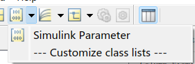
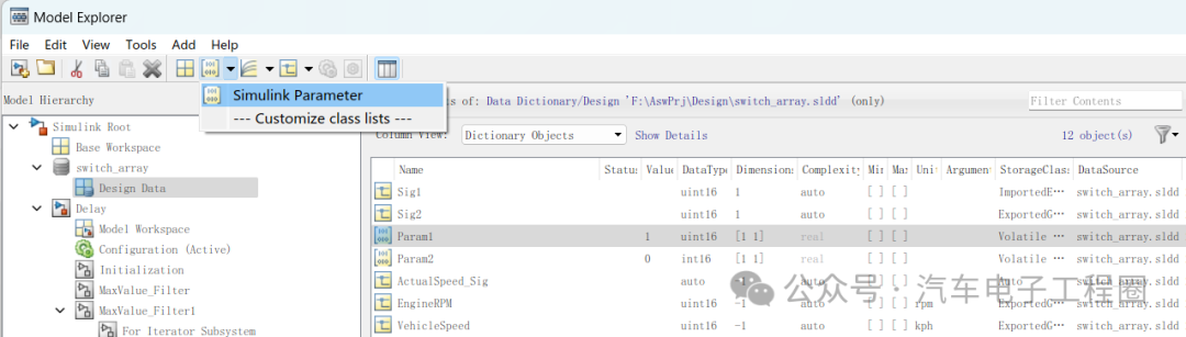
1) Creating an Object (in the Data Dictionary):
Right-click on the <span><span>Design Data</span></span> node in the data dictionary -> <span><span>Add</span></span> -> <span><span>Simulink Parameter,</span></span> and name the object as shown in the following figure: Param1:
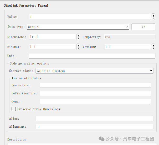
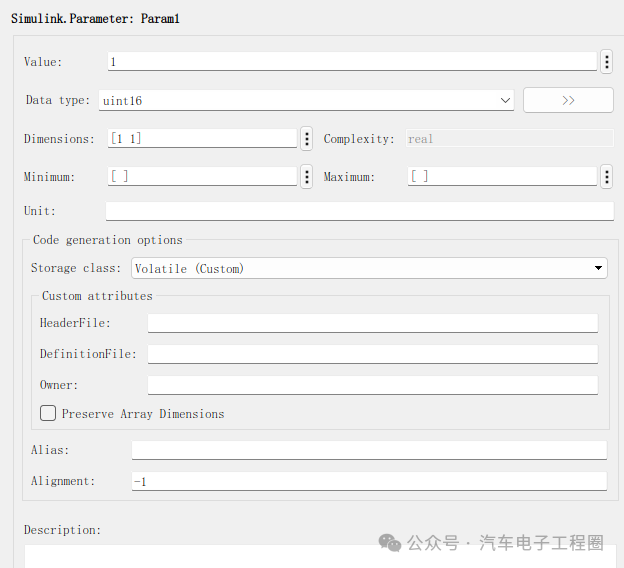
2) Configuring Attributes:
Set key attributes in the property pane on the right side of <span><span>Model Explorer</span></span>, as shown below:
3) Associating with Module Parameters:
In the Simulink model, double-click the module that needs parameter configuration (such as Gain, Constant, Lookup Table n-D, etc.) to open its parameter dialog box, taking Constant as an example.
In the corresponding parameter value field (such as the Constant Value field of the Constant module), enter the name of the Simulink.Parameter object defined in the data dictionary (Param1).
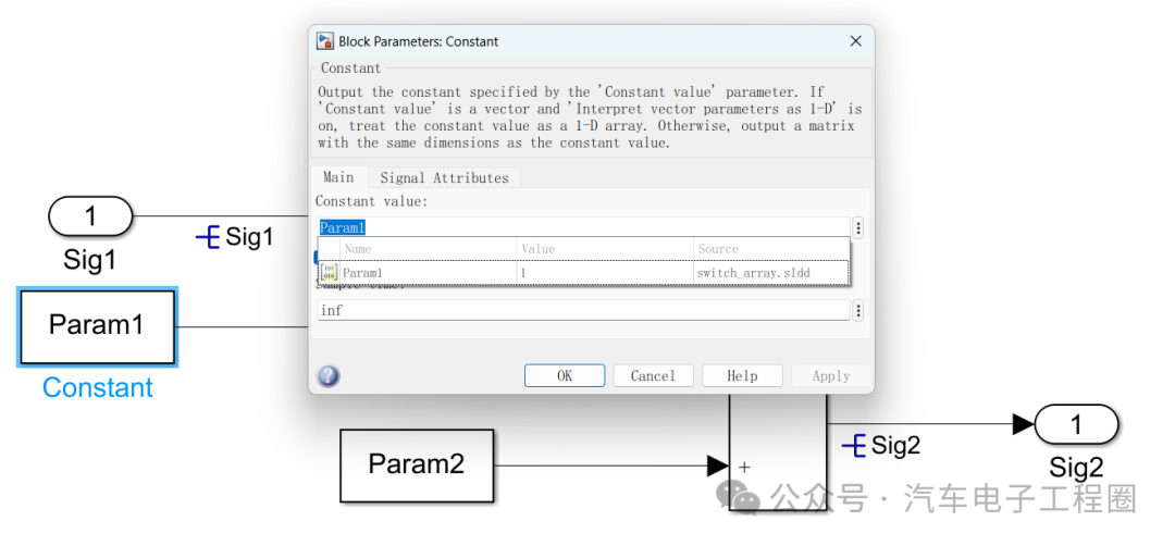
When the model is compiled or updated, Simulink will retrieve the <span><span>Value</span></span> property value of the <span><span>Parameter</span></span> object from the data dictionary and apply it to the module parameter. At the same time, the data type, dimensions, etc., of the module parameter will also be constrained by the corresponding attributes of the <span><span>Parameter</span></span> object.
2 Application of Simulink.Parameter in ECU Application Model Development
In ECU (Electronic Control Unit) application model development, <span><span>Simulink.Parameter</span></span> is mainly used to define parameters, such as concentrating the constant parameters used in the model (e.g., control thresholds, scaling factors, calibration values, etc.) in the <span><span>Simulink.Parameter</span></span> object for unified viewing, modification, and maintenance; and for parameters that need to be adjusted during actual ECU operation or later calibration stages, <span><span>Simulink.Parameter</span></span> can be configured as “tunable parameters” to achieve offline or online calibration with ECU calibration tools without recompiling the model. Common examples include:
-
PID Controller: Define
<span><span>Simulink.Parameter</span></span>objects<span><span>P_Gain</span></span>,<span><span>I_Gain</span></span>,<span><span>D_Gain,</span></span>so that the gain values are encapsulated and defined with clear value ranges and data types, and in the generated code, they are global variables that can be adjusted at runtime through calibration tools. -
Lookup Table Data: Define a
<span><span>Simulink.Parameter</span></span>object<span><span>EngineTorqueMap</span></span>, set the<span><span>Value</span></span>to<span><span>[1000, 2000, 3000; 50, 150, 250]</span></span>(representing the RPM-throttle-torque mapping table),<span><span>DataType</span></span>set to<span><span>single</span></span>, and<span><span>Dimensions</span></span>set to<span><span>[2, 3]</span></span>. Associate it with the<span><span>Table data</span></span>parameter of the Lookup Table (2-D) module. This centrally manages the table data and its attributes. -
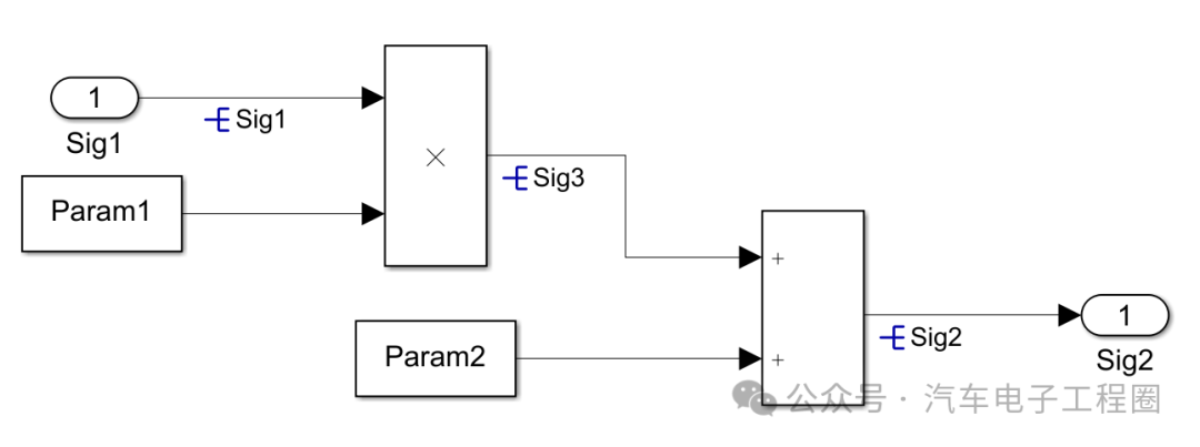
Conversion Coefficients: Define
<span><span>Simulink.Parameter</span></span>objects Param1 and Param2, as shown below:

Of course, there are other uses, which will not be detailed here.
Considering that <span><span>Simulink.Signal</span></span> and <span><span>Simulink.Parameter</span></span> are the two core objects of the ECU application layer model data dictionary, let’s briefly compare the two:
3. <span><span>Simulink.Signal</span></span> vs. <span><span>Simulink.Parameter</span></span> Differences and Relationships
Both allow for fine control of data attributes (whether signals or parameters), which is crucial for model quality, simulation accuracy, and efficient code generation. They are often used together in the same data dictionary to define the complete data interface and configuration of the model. The specifics are shown in the table below:
| Feature | <span><span>Simulink.Signal</span></span> |
<span><span>Simulink.Parameter</span></span> |
Relationship |
|---|---|---|---|
| Core Representation | Data flowing on signal lines (dynamic) | Values of module parameters (static/configured) | Both are data objects used to manage data in Simulink models. |
| Stored Content | Metadata (describing signal attributes) | Value + Metadata (including specific values and descriptive attributes) | Both contain metadata describing data characteristics (<span><span>DataType</span></span>, <span><span>Dimensions</span></span>, <span><span>Complexity</span></span>, etc.). |
| Value Storage | Does not store specific values (stores initial value <span><span>InitialValue</span></span>) |
Stores specific values (<span><span>Value</span></span> property) |
|
| Main Use | Defines signal attributes, bus elements, states, control code signal representations | Defines module parameter values, constants, tunable parameters, control code parameter representations | Both are used for precise control of data types, dimensions, and other attributes. |
| Target Object | Associated with signal lines (resolved by signal name) | Associated with module parameter dialog | |
| Dynamic Nature | Represents data flow that may change during model execution | Represents typically fixed or runtime-tunable configurations/constants | <span><span>Signal</span></span> ‘s <span><span>InitialValue</span></span> is parameter-like; <span><span>Parameter</span></span> can be tunable. |
| Code Generation | Controls signal variable declarations (global variables, external variables, etc.) | Controls parameter representations (<span><span>#define</span></span>, <span><span>const</span></span>, global variables, etc.) |
Both control representations and storage methods in generated code through <span><span>Storage Class</span></span> and other attributes. |
| Typical Examples | Sensor signals, control commands, state variables, bus elements | PID gains, physical constants, lookup table data, thresholds, sampling times |
<span><span>Considering that there are overlaps in the usage of both in practical applications, let's review the differences between the two based on the above table:</span></span>
-
<span><span>Signal</span></span>is a descriptor of data flow (line), while<span><span>Parameter</span></span>is a container for configuration values (point). -
Signal objects themselves do not store the real-time values flowing on the signal line during simulation; they only define the attributes of that signal. The values of the signal during simulation are determined by the module that generates it.
-
Parameter objects store the specific value of the parameter they represent (
<span><span>Value</span></span>property), which will be directly used in the associated module parameters. -
You select a signal line in the model and apply a
<span><span>Signal</span></span>object; you enter the name of a<span><span>Parameter</span></span>object in the module’s parameter dialog to apply it.
Creating content is not easy, feel free to like, save, and follow for more!! (Qian Yixing changed name Automotive Electronics Engineering Circle) Automotive R&D exchange group, interested friends please add the group owner: prOmiseyes, note: company + position to join the group. Limited to automotive practitioners.
Series of articles on ECU application layer software models are continuously updated, teaching you application layer development from scratch:
- Example 1 of building ECU application layer software model (qq.com)
- How to automatically generate code for ECU application layer software model 2 (qq.com)
- How to run ECU application layer software periodically 3 (qq.com)
- Code generation configuration related to hardware for ECU application layer software model 4 (qq.com)
- Data dictionary of ECU application layer software model DD 5 (qq.com)
- Storage classes of data dictionary in ECU application layer software model 6 (qq.com)
- Fixed-point implementation methods for ECU application layer software model 7 (qq.com)
- Five fixed-point implementation methods for ECU application software model 8 (qq.com)
- Custom storage classes for ECU application layer software model 9 (qq.com)
- Summary of model generation code for ECU application layer software model 10 (qq.com)
- CAN reception in ECU application layer model 11 (qq.com)
- Data stream of CAN message reception in ECU application layer model 12
- How to leverage AI in ECU software development? Application of Kimi in MBD development environment 13
-
Detailed explanation of unit test coverage CC, DC, and MCDC in ECU application layer software model 14
-
Application and Principles of Calibration and Observables in ECU Application Layer Model Development 15
-
Usage of for loop in ECU application layer model development 16
- Usage of if-else in ECU application layer model development 17
- Initialization function in ECU application layer model development 18
-
Counter in ECU application layer model development 19
-
Basics of Assignment module in ECU application layer model development 20
-
Application of Delay module in ECU application layer model development 21
-
ECU application layer model development: If-else vs. switch-case 22
-
Data dictionary of ECU application layer model development: Simulink.Signal 23
-
Data overflow handling in ECU application layer model development 24
-
Disasters caused by Delay in ECU application layer model development 25
-
Usage of Tapped Delay in ECU application layer model development 26
-
First-order low-pass filtering in ECU application layer model development 27