
RS-485 Communication Network Structure Diagram (Including Terminal Resistance Settings)
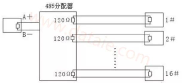
Structure 1
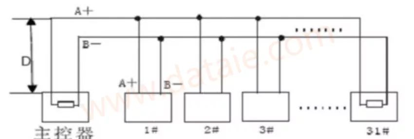
Structure 2
RS-485 Bus Transmission Distance
When using 0.56mm (24AWG) twisted pair as communication cable, the maximum theoretical transmission distances based on different baud rates are as follows:
|
Baud Rate |
Distance |
|
2400Bps |
1800m |
|
4800Bps |
1200m |
|
9600Bps |
800m |
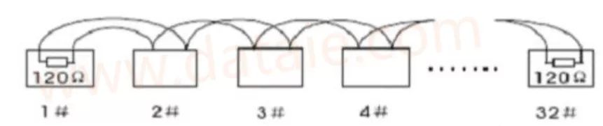
RS-485 Bus Standard Reference Structure


For more PLC wireless communication materials, please follow “PLC Wireless Communication Solutions”