
1
Introduction:
RS-485 is a standard protocol for transmitting data that can be used to establish a reliable, high-speed, real-time, multi-node data communication network connection. RS-485 is also known as TIA-485. RS-485 defines the electrical characteristics of drivers and receivers used in serial communication systems. RS-485 is widely used in industrial control systems, handling up to 32 devices on a single network. It is commonly utilized in industrial automation for monitoring and controlling PLCs, variable frequency drives, DCS, etc. This article will mainly introduce the basic principles, characteristics, wiring, and practical application cases of RS-485 communication.
2
Basic Principles of RS-485 Communication:
RS-485 is an asynchronous serial communication protocol that enables multi-node communication. RS-485 communication is based on differential signaling, where information is transmitted through two wires (commonly referred to as A and B) carrying two complementary signals. The voltage difference between these two wires conveys the information, rather than the voltage between a single wire and ground. This makes RS-485 systems highly resistant to common-mode noise, enhancing transmission distance and speed. The RS-485 protocol allows one master node to communicate with up to 32 slave nodes, with communication between nodes coordinated through the master node.

3
Characteristics of RS-485 Communication:
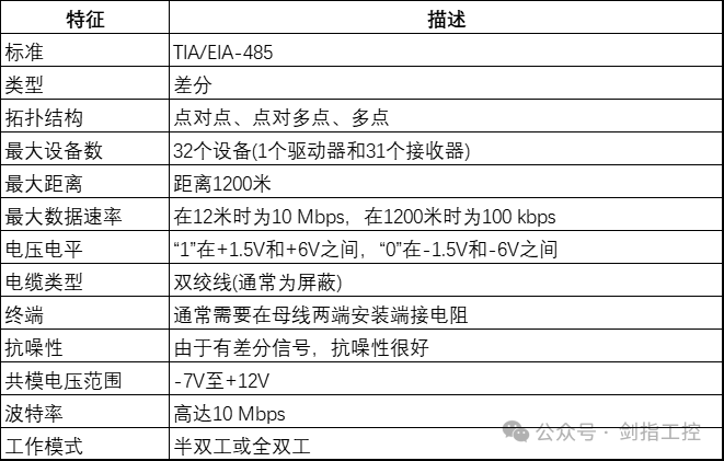
RS-485 communication is characterized by high speed, reliability, stability, real-time capability, and low cost. Since RS-485 supports multi-node communication, it eliminates the need for complex signal forwarding mechanisms and simplifies network expansion. The RS-485 protocol is standardized, avoiding compatibility issues, and due to the application of differential transmission technology, RS-485 communication has high resistance to electromagnetic interference. Additionally, RS-485 communication can maintain stability and reliability over communication distances of up to 1.2 kilometers. RS-485 signals can be transmitted without confirmation. Interruptions or interference in differential signals can corrupt data without repetition or acknowledgment; a “send and forget” system.
The main characteristics are summarized in the table below:
4
Wiring of RS-485:
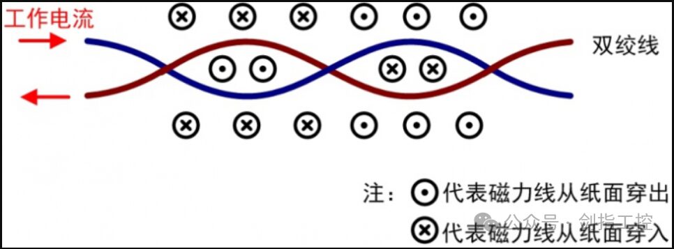
Wiring for RS-485 needs to use a twisted pair mechanism as shown in the figure below, laying out the twisted pair of data lines. Additionally, since RS-485 uses differential signaling for transmission, we also need to provide a common signal ground for the two data lines. To avoid interference from other signals, we can include RS-485 interference-resistant attenuators in the wiring.
5
RS-485 Communication Example:
Let’s consider a simple example of an RS-485 network with one master device and two slave devices.
Idle State: When no device is transmitting, the line is in an idle state. In this state, the differential voltage between line A and line B is zero.
Master Transmission: When the master device wants to send data, it will change the voltage difference between line A and line B. For example, “1” may indicate that A’s voltage is higher than B, while “0” may indicate that B’s voltage is higher than A.
Slave Reception: All devices on the network (including slave devices) continuously monitor the voltage difference between line A and line B. When they detect a change, they interpret it as some data.
Slave Response: If the command sent by the master device requires a response from the slave device, that slave will wait until the master has finished transmitting, then change the voltage difference between line A and line B to send its response.
Master Receives: The master device, like the slave devices, continuously monitors the voltage difference between line A and line B, so it will receive responses from the slave devices.
Return to Idle State: After all data has been transmitted, the line returns to the idle state, with a voltage difference of zero between lines A and B.
In this way, data can be sent back and forth over the RS-485 network. It is important to note that all devices on the network need to use the same logic to interpret the voltage differences as bits (i.e., whether A’s voltage being higher than B represents “1” or “0”). In a network with multiple devices, each device needs to have a unique address so that it knows when to listen and when to ignore communication on the line. This is typically handled by the protocols used above RS-485, such as Modbus or Profibus.
For example, in a Modbus network, every message sent by the master station begins with the address of the target device. When devices see a message with their address, they know to process that message and may send a response. If the address does not match their own, they ignore the message.
6
Conclusion:
Compared to protocols like TCP/IP, USB, and I2C, while RS-485 may not have particularly high transmission speeds, it has unparalleled advantages: enabling multi-node communication, strong resistance to interference, and long communication distances—features that other protocols cannot match. As a communication protocol widely used in industrial control and automation fields, RS-485 has a very broad future application prospect.
March 2024
1.Smart200&V90 Servo System: Updated 15 Courses
2.B&R Live Courses: Updated 30 Courses
3.PKS Quick Start: Beginner & Intermediate – Full