1. Introduction
When learning about the 51 microcontroller, we often use the combination of Keil and Proteus for experiments. This simulation saves us a lot of hardware and time costs, allowing us to visually observe the execution process of the code. However, when switching to the STM32 series microcontrollers, Proteus is obviously not supported, but the simulation function of Keil is still very useful. For example, with the STM32F103 microcontroller, we can achieve good simulation effects in Keil, where we can use interrupts, timers, PWM, etc., and observe the output of GPIO. However, Keil does not support the STM32 series microcontrollers very well; if you change the model, you will find that it cannot simulate at all!!!
2. Configuring Keil to Simulate STM32 Series Microcontrollers
We can modify certain settings to enable Keil to simulate STM32.
1) First, modify the content of the “debug” tag
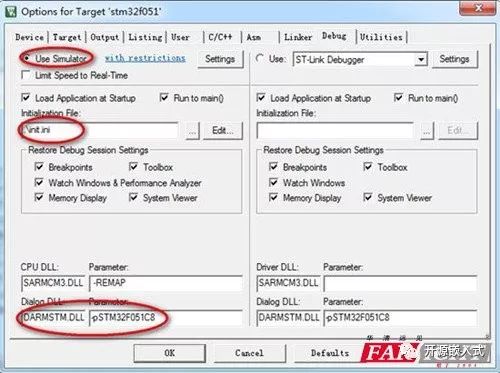
“Use simulator” indicates that software simulation is to be used.
The content of “dialog DLL” is “DARMSTM.DLL”, indicating the use of STM series.
The content of “parameter” is “-pSTM32F051C8”, which matches the current microcontroller model.
2) Initialization file
Let’s take a look at the content of this file.
map 0x40000000,0x4000ffff read write
map 0x40010000,0x4001ffff read write
map 0x40020000,0x4002ffff read write
map 0x48000000,0x4800ffff read write
This segment is actually setting the read/write characteristics of the microcontroller’s memory addresses. The above addresses are all readable and writable. The C language continuously addresses in memory and executes instructions. So why are these addresses used? You can refer to the memory mapping of the STM32F051 microcontroller.
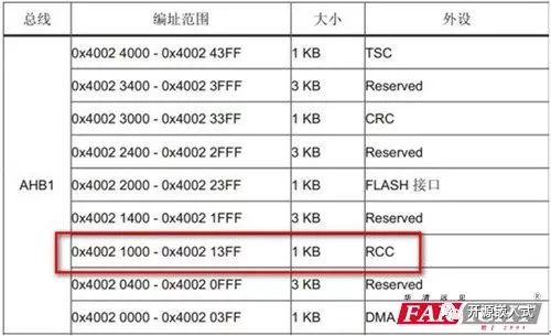
The above is just a portion of the memory mapping; this is the address of AHB2. For example, if you want to use the RCC function, you can see that the address range 0x40021000•0x400213ff needs to have read/write attributes.
3. Tracking a Variable
1) Find the Logic Analyzer
After completing the basic configuration, we can start debugging.

The debug button is self-explanatory; there is a button in the middle for the logic analyzer, which we can click to activate the logic analysis function. The logic analyzer can help us observe a specific model graphically.
2) Add Variables to the Logic Analyzer
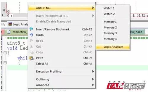
Position the mouse to the left of the global variable x, right-click–>add x to–>logic analyzer, thus adding the variable x to the logic analyzer window. If you click run at this point, you can see the curve of variable x in the window.
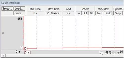
3) Modify Display Effects
From the above image, we can see that since x is a uint8 type variable, its value range is 0~255. However, sometimes it is hard to observe the changes in x, so I need to modify the display effect of the logic analyzer. Click setup, and the following dialog will pop up, allowing us to change the display color and range of x.
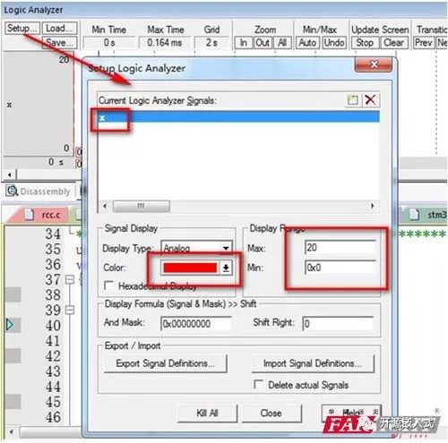
The modified display effect shows that x increases every 2 seconds, which corresponds to the logic of the code.

4. Using SysTick
The reason the variable x shows an increment every 2 seconds is that we used the HAL_Delay function from the Cube library for delays; let’s take a look at the code.
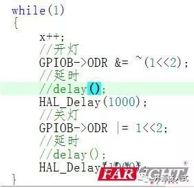
In the Cube library, this delay function uses the SysTick feature. If the simulated graph shows that x does not change, it may be because your SysTick function is not configured correctly.
1) Click peripheral—core peripheral—system tick timer
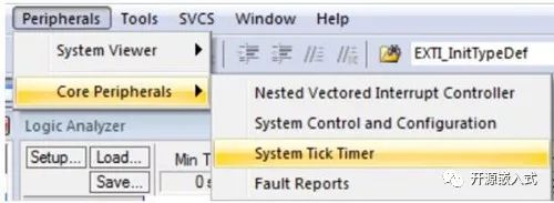
2) Enable SysTick as shown below
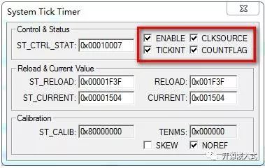
3) Remove waiting in the code
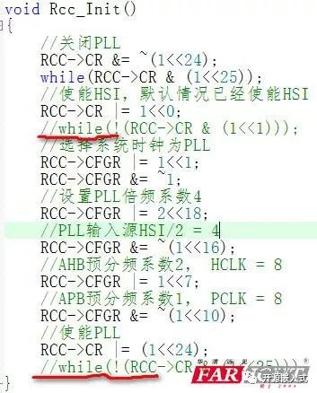
If you have any waiting states in your clock configuration code, you need to disable them; otherwise, it will not simulate correctly.
5. Tracking GPIO
If your code needs to output a PWM wave, the logic analyzer is the best tool for measurement. However, if you do not have a logic analyzer, you can still simulate it using software. Now, suppose I use the STM32F051C8 chip to output a PWM waveform on the PB2 pin; let’s simulate it.
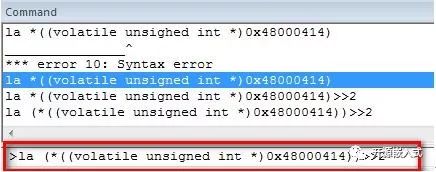
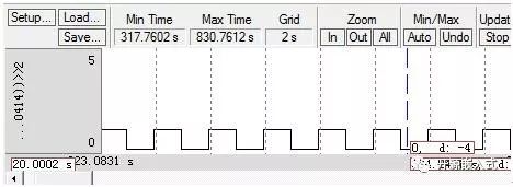
At the bottom of the Keil software, we can see a command window where we can enter a command:
La (*((volatile unsigned int *)0x48000414))>>2 The command above is used to track a variable in the logic analyzer, and the address of this variable is the bit 2 of 0x48000414. Referring to the manual, you can see that this address corresponds to PB2. Thus, we can see the results below.