JTAG is a commonly used interface for debugging devices. When there are many devices, a JTAG daisy chain can be used to save external interfaces, resulting in fewer external connection wires. The connection method is shown in the figure below: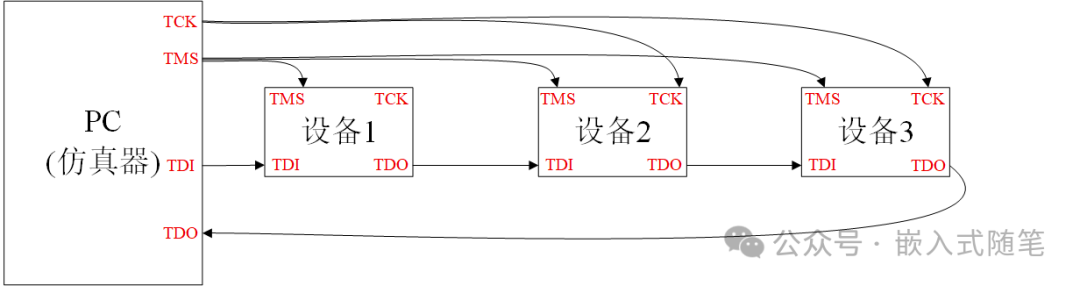 When sending and receiving data, it is necessary to determine the data to be received and sent based on each device. How does each device identify the data sent to itself? The JTAG data transmission and reception use state machine transitions:
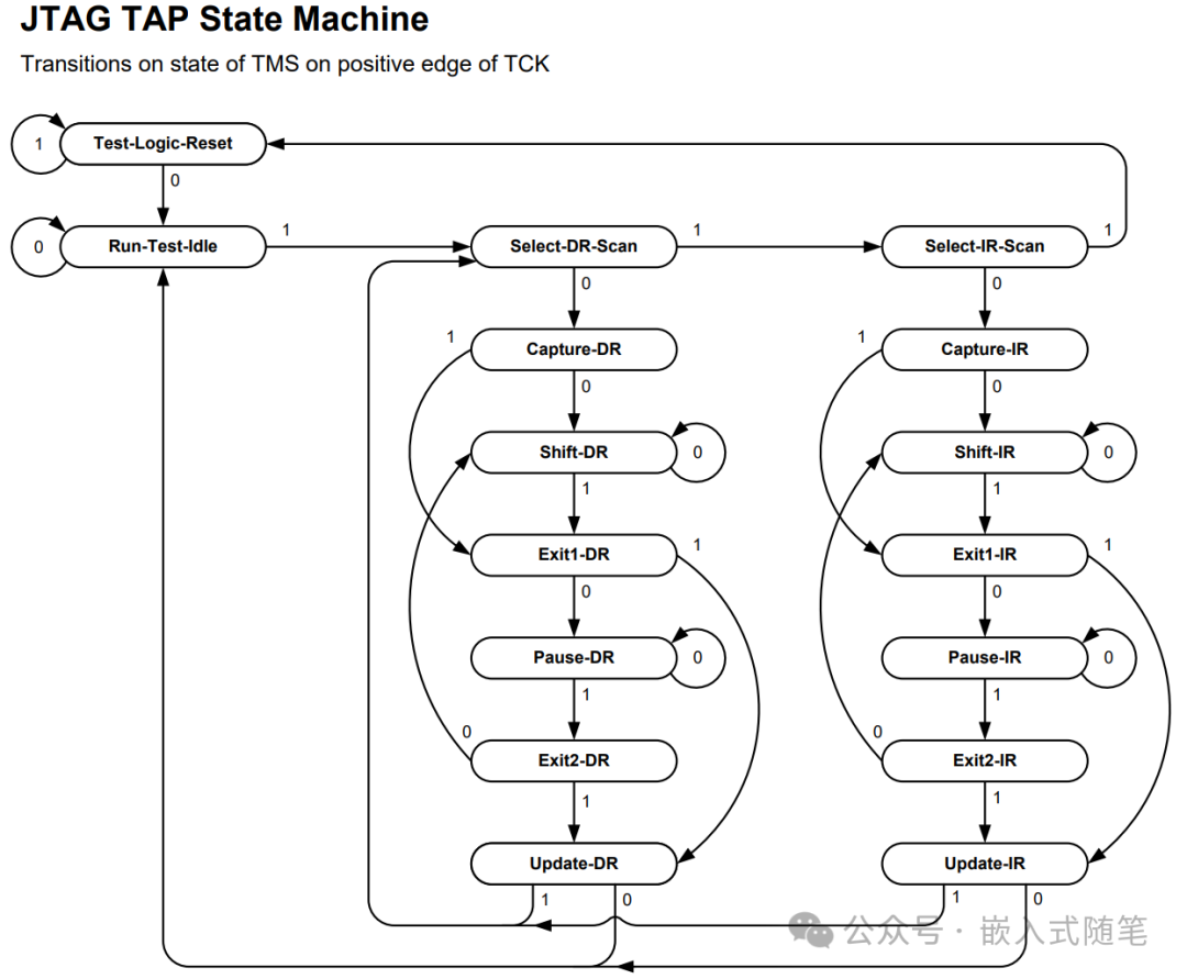 Data is sent serially along the time axis. Since TMS and TCK are connected in parallel to each device, state transitions occur synchronously. Each device synchronously reads and writes data. The following figure illustrates this:
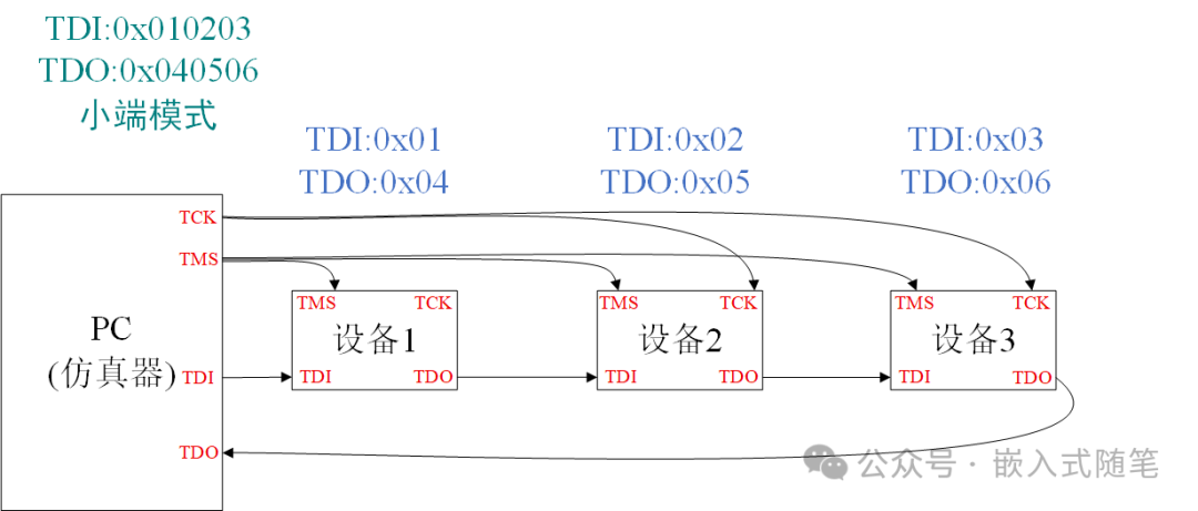 Assuming TDI needs to send 0x010203, which consists of three bytes, each byte is received one at a time. TDO[0]=0x03, TDI[1]=0x02, TDI[2]=0x01. First, 0x03 is sent, then 0x02, and finally 0x01. On the clock axis, as time progresses, the first sent data 0x03 reaches the farthest device 3, while the last sent 0x01 reaches the nearest device 1.Thus, when 0x01 is sent to device 1, 0x03 has already been transmitted to device 3. At this point, a state machine transition occurs, and device 1 retrieves data 0x01, device 2 retrieves data 0x02, and device 3 retrieves data 0x03. In this way, each device obtains the data it requires.
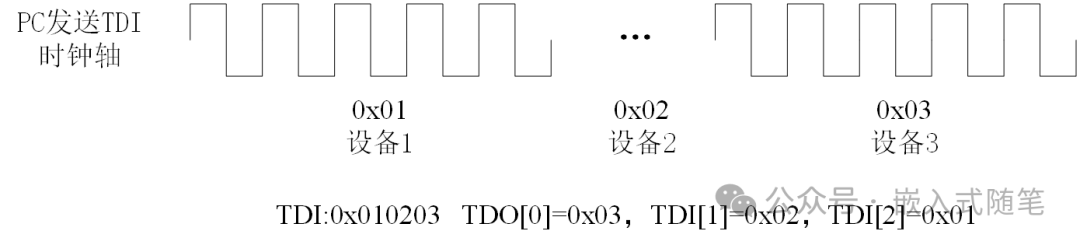 Assuming TDO, three devices need to send 0x04, 0x05, and 0x06. Device 3 sends 0x06, device 2 sends 0x05, and device 1 sends 0x04.At the moment of state transition, the data sent by device 1 enters device 2’s TDI, the data sent by device 2 enters device 3’s TDI, and the data sent by device 3 enters the PC’s TDO. Thus, the data serially enters the PC, with the data from the nearest device to the PC being received first.As shown in the figure below, TDO first receives 0x06 from the nearest device 3, followed by 0x05 and 0x04. Therefore, the overall received data is 0x040506.
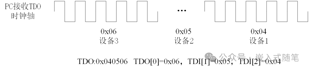 The terms “farthest” and “nearest” refer to the physical distance of the TDI and TDO connections to the PC. In this way, each device can receive the data it needs.For the emulator, taking IAR as an example, as shown in the figure below:
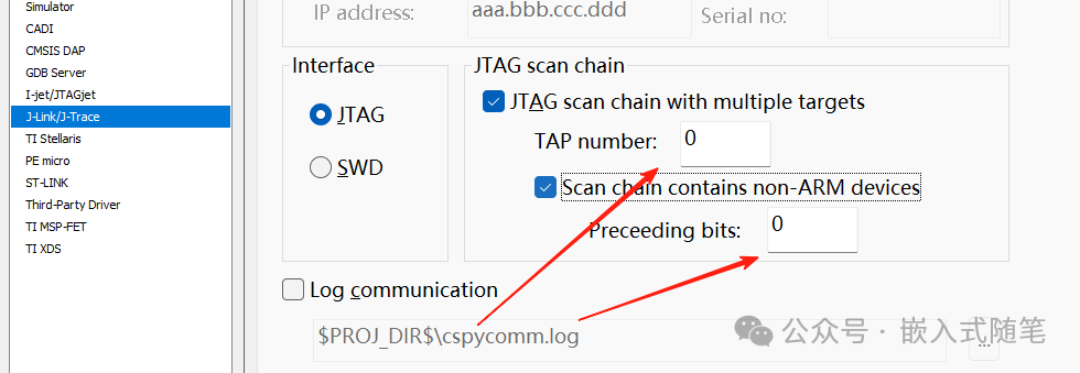 TAP is the number of devices from TDO (excluding itself), and Preceding bits are the number of TAP controller (IR) bits from TDO (excluding itself). This way, the emulator can read and write the corresponding data.