Tell a moving story, write understandable code
When an embedded development novice (both an embedded development rookie and a programming rookie) reads the following description ofBSP, HAL, and PAC, the core concepts of embedded development, they often feel confused.
The Board Support Crate (BSP) is responsible for providing a unified abstraction for the entire development board (such as micro:bit). It needs to provide an abstract interface for the microcontroller and devices on the board, such as sensors and LEDs. For custom development boards, there is usually no ready-made BSP available. In this case, you need to use the chip’s HAL and develop sensor drivers yourself or look for them on crates.io. Fortunately, micro:bit already has a ready-made BSP called microbit-v2, so we can use it directly on top of HAL.
The Hardware Abstraction Layer (HAL) is built on top of the chip’s PAC, providing an easy-to-use abstract interface for developers who are not familiar with the chip’s characteristics. HAL typically abstracts each peripheral as an independent structure, allowing developers to easily perform operations such as data transmission. If developing embedded programs for the micro:bit v2 development board, we will use nRF52-hal.
Next, let’s explore a core software component in the Rust embedded world:<span><span>embedded-hal</span></span>. As its name suggests, it is closely related to the second level of abstraction, the HAL layer.<span><span>embedded-hal</span></span> provides a set of traits to describe the common behaviors of specific peripherals in all HAL implementations. For example, it defines the basic functions to control the power switch of pins, enabling us to control the LED lights or other devices on the development board.<span><span>embedded-hal</span></span> allows us to develop generic hardware drivers (such as temperature sensor drivers) that can run on any chip implementing the <span><span>embedded-hal</span></span> traits. This universality is achieved by relying solely on the <span><span>embedded-hal</span></span> traits. Drivers written this way are called platform-independent. Fortunately, most drivers on <span><span>crates.io</span></span> adopt this platform-independent design.
The Peripheral Access Crate (PAC) provides a relatively safe direct access interface to the chip’s peripherals, allowing developers to control each register bit precisely (of course, it may also be configured incorrectly). Typically, PAC is only needed when higher-level abstractions cannot meet the needs or when developing higher-level code. If developing embedded programs for the micro:bit v2 development board, we will mainly use the nRF52 PAC implicitly.

Now, let’s analyze a simple example: using Rust code to light up an LED on the micro:bit v2 development board (as shown in Figure 1). Through this example, we will gain a deeper understanding of what the concepts of BSP, HAL, embedded-hal, and PAC are all about.
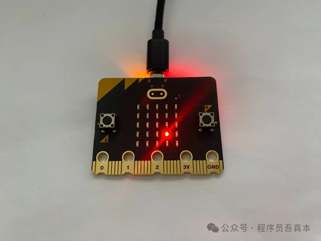
Figure 1: Using Rust code to light up an LED on the micro:bit v2 development board
Before diving deeper, let’s take a look at the code.
Rust Code to Light Up the LED
The complete code for this article can be found in the learn-rust-by-games repository under the ch01/lu1l directory of the github account wubin28. If you want to run this code, you only need to spend the price of two or three cups of coffee to buy a micro:bit v2 development board, and then follow the steps in Chapter 1 of “Learning Rust for Beginners: From Lighting Up LEDs to Mastering Programming” (Simplified Version). Below are two source code files related to this article.
Rust Source Code Entry File: src/main.rs
The Rust source code entry file src/main.rs is shown in Listing 1:
Listing 1: ch01/lu1l/src/main.rs
// Disable unsafe code#![deny(unsafe_code)]// Declare that this is a standalone program, not using the standard entry point#![no_main]// Not using the standard library, which is common in embedded systems#![no_std]// Import necessary embedded development libraries// Specify the program entry pointuse cortex_m_rt::entry;// Hardware interface operationsuse embedded_hal::digital::OutputPin;// Control the development boarduse microbit::board::Board;// Import panic runtime error handleruse panic_halt as _;// Program entry point#[entry]fn main() -> ! { // Return ! indicates this is a non-returning function // Take control of the microbit board let mut board = Board::take().unwrap(); // Light up the LED at row 4, column 4 of the LED matrix, // setting column 4 to low while setting row 4 to high board.display_pins.col4.set_low().unwrap(); board.display_pins.row4.set_high().unwrap(); // Infinite loop to keep the program running loop {}}Generic Rust Project Package Management File: Cargo.toml
The generic Rust project package management file Cargo.toml is shown in Listing 2:
Listing 2: ch01/lu1l/Cargo.toml
[package]# Project namename = "lu1l"# Project version numberversion = "0.1.0"# Rust version requirement (2021 edition)edition = "2021"# Dependencies and their version numbers[dependencies]# Cortex-M runtime supportcortex-m-rt = "0.7.3"# Provides panic handling mechanism, stops running when the program crashespanic-halt = "0.2.0"# BBC micro:bit v2 development board support packagemicrobit-v2 = "0.15.0"# Embedded hardware abstraction layer interfaceembedded-hal = "1.0.0"Cargo.toml is the core configuration file for Rust projects, recording basic information about the project such as project name, version number, and required dependencies.
🧠 Why do we need to list these dependencies under <span><span>[dependencies]</span></span> in Cargo.toml? What will happen if we remove them? Can you identify which lines of code in main.rs correspond to these dependencies?
💡 Let’s discuss why it is necessary to list these dependencies in Cargo.toml and how they work with the code in main.rs. First, the <span><span>cortex-m-rt</span></span> package acts like a starter, responsible for initializing the Cortex-M processor and handling the program’s startup process. In the code, we use <span><span>use cortex_m_rt::entry</span></span> and <span><span>#[entry]</span></span> annotations to use it. Without this package, the program cannot start because there is no entry point.
Next is the <span><span>panic-halt</span></span> package. Its role is to put the system into a safe halt state when a serious error occurs in the program. The code <span><span>use panic_halt as _</span></span> is using it. In embedded environments, we must have such an error handling mechanism, otherwise the compiler will remind us of the lack of necessary safety guarantees.
The <span><span>microbit-v2</span></span> package is our main character, providing all the functions to interact with the development board. When we write <span><span>use microbit::board::Board</span></span> in the code, we are calling the functions provided by this package. Without it, we cannot control any components on the development board.
Finally, the <span><span>embedded-hal</span></span> package acts like a universal translator, defining standard interfaces for controlling hardware. In the code, we use <span><span>use embedded_hal::digital::OutputPin</span></span> to operate pins. This package allows us to control different hardware devices in a unified manner.
If any of these dependencies are removed, our code will not work like a machine missing parts. This is because:
-
Each of these packages serves an indispensable foundational function -
There is a close collaborative relationship between them -
In this special environment of embedded development, they collectively provide the necessary system support
Why is it not enough to only use microbit-v2 to light up the LED?
🧠 Why is it not enough to just use the <span><span>microbit-v2</span></span> dependency, and why is the <span><span>embedded-hal</span></span><span><span> dependency also needed to light up the LED? How do these two dependencies work together?</span></span>
💡 Let’s discuss why it is not enough to only use the <span><span>microbit-v2</span></span> dependency and why the <span><span>embedded-hal</span></span><span><span> dependency is also needed to light up the LED. This question involves the collaboration mechanism between dependencies.</span></span>
First, <span><span>microbit-v2</span></span>, as a Board Support Package, acts like a butler, managing the entire development board. But the butler needs a set of standard, platform-independent rules to operate various devices, including the LED lights. Such standard rules allow the same operation methods to be applied across different hardware platforms (like the micro:bit v2 platform discussed in this article, or Arduino, STM32, ESP32 platforms).
At this point, <span><span>embedded-hal</span></span> serves as a universal operation manual that defines standard interfaces (such as the <span><span>OutputPin</span></span><span><span> trait). It tells the butler: "To turn on or off a device, you need to follow these rules." This allows different hardware managers to work in a unified manner.</span></span>
Their collaboration is as follows:<span><span>microbit-v2</span></span>, this professional butler, controls the hardware through the standard methods provided by <span><span>embedded-hal</span></span><span><span>. When we want to light up an LED, the butler will use the </span></span><code><span><span>OutputPin</span></span><span><span> trait defined by </span></span><code><span><span>embedded-hal</span></span><span><span> to accomplish this task.</span></span>
To light up the LED, in addition to the butler and the standard operation manual, we also need the specific execution team: the “project manager” implementing <span><span>embedded-hal</span></span><span><span> for the nRF52833 platform, </span></span><code><span><span>nrf52833-hal</span></span><span><span>, and the "specialist" that the project manager relies on, </span></span><code><span><span>nrf52833-pac</span></span><span><span>.</span></span>
What is the relationship between BSP, embedded-hal, HAL, and PAC?
Let’s first look at the responsibilities of each member in this team:
<span><span>main()</span></span>
function -
As the main controller of the program, responsible for issuing commands -
Decides when to initialize the development board and how to control the LED matrix -
Interacts directly with <span><span>microbit-v2</span></span>. <span><span>microbit-v2</span></span>
(Board Support Crate, also known as Board Support Package, BSP) Board Support Package -
Serves as the exclusive manager of the micro:bit v2 development board -
Knows the location of all devices such as the LED matrix and buttons -
Executes specific operations through <span><span>embedded-hal</span></span>and<span><span>nrf52833-hal</span></span><span><span>.</span></span> <span><span>embedded-hal</span></span>
(Hardware Abstraction Layer, HAL) Platform-independent hardware abstraction layer -
Defines standard specifications for device operations -
Provides <span><span>OutputPin</span></span><span><span> and other common interfaces</span></span> -
Unifies the control methods for different devices <span><span>nrf52833-hal</span></span>
(Hardware Abstraction Layer, HAL) Hardware abstraction layer for the nRF52833 platform -
Acts as the coordinator for the nRF52833 chip, focusing on functional implementation and sending commands to the PAC layer -
Follows and implements the standards defined by <span><span>embedded-hal</span></span><span><span>.</span></span> -
Provides safe operation interfaces <span><span>nrf52833-pac</span></span>
(Peripheral Access Crate, PAC) Peripheral access package for the nRF52833 platform -
Acts as the low-level executor for the nRF52833 chip, responsible for specific hardware operations -
Manages the physical address mapping of devices -
Provides the most basic hardware control functions
The relationship between these components can be represented by the following UML class diagram, as shown in Figure 2:
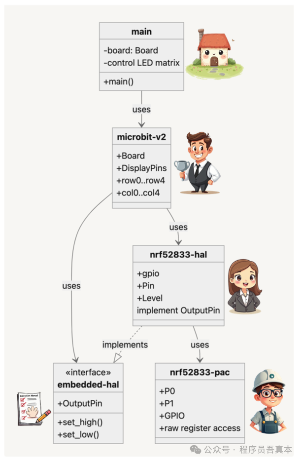
Let’s take a closer look at the architectural design of this UML class diagram. This is a typical layered architecture for embedded systems, progressing from the application layer to the hardware access layer.
Starting from the top layer:
-
The application layer (main, like the owner of the house) is where the user code resides, controlling the LED matrix through the Board interface without worrying about the underlying implementation details. -
The Board Support Package ( <span><span>microbit-v2</span></span><span><span>, like a butler) serves as an adaptation layer, encapsulating the specific hardware of the development board (such as the row and column pins of the LED matrix) into easy-to-use interfaces. It relies on the </span></span><code><span><span>embedded-hal</span></span><span><span> interface to operate GPIO, making it adaptable to any hardware platform that implements the </span></span><code><span><span>embedded-hal</span></span><span><span> interface.</span></span> -
The Hardware Abstraction Layer interface ( <span><span>embedded-hal</span></span><span><span>, like a platform-independent operation manual) defines standard hardware operation interfaces (such as </span></span><code><span><span>OutputPin</span></span><span><span>). This is key to achieving cross-platform compatibility, as it declares basic GPIO operations like </span></span><code><span><span>set_high()</span></span><span><span> and </span></span><code><span><span>set_low()</span></span><span><span>.</span></span> -
The hardware abstraction layer implementation ( <span><span>nrf52833-hal</span></span><span><span>, like the project manager of the nRF52833 chip) implements the </span></span><code><span><span>embedded-hal</span></span><span><span> interface for the nRF52833 chip. It is responsible for converting abstract GPIO operations into corresponding register operations while providing safe access mechanisms.</span></span> -
The peripheral access layer ( <span><span>nrf52833-pac</span></span><span><span>, like the specialist for the nRF52833 chip) provides the lowest level of register access functionality, directly interacting with the hardware. It encapsulates the read and write operations of hardware registers, but it is generally not recommended for upper layers to use directly.</span></span>
The advantages of this layered design include:
-
Implementing hardware abstraction through the <span><span>embedded-hal</span></span><span><span> interface allows application code to be easily ported to other platforms</span></span> -
The BSP layer converts low-level GPIO operations into LED matrix control interfaces that better meet application needs -
Layered encapsulation reduces the risk of directly operating hardware, providing a safer development environment -
Each layer has clear responsibilities, making code maintenance and unit testing easier
The dependency relationships in the diagram clearly illustrate the interaction methods between layers: solid arrows indicate “uses” relationships, while dashed hollow arrows indicate “implements” relationships. This design maintains good decoupling while fully utilizing hardware characteristics.
🧠 What is GPIO?
💡 This is the basic hardware interface in embedded systems, full name General Purpose Input/Output, primarily used for implementing digital signal input and output.
Its main characteristics and functions are as follows:
-
It has excellent programmability. Each GPIO pin is like a flexible switch that can be set to input or output mode as needed. -
In input mode, it acts like a careful scout, reading various external signals, such as the state of button presses or changes in sensor states. -
In output mode, it becomes a commander, controlling the behavior of external devices, whether lighting up an LED or driving a motor. -
In output mode, GPIO can output two digital levels, similar to the two states of a switch: -
High level corresponds to the “on” state, usually a voltage of 3.3V or 5V -
Low level corresponds to the “off” state, usually 0V or ground
In our UML diagram, you can see how the micro:bit v2 development board cleverly utilizes GPIO. Each LED is like a small light bulb, controlled by the combination of row and column pins. By appropriately adjusting the levels of these GPIO pins, we can achieve precise control over specific LEDs, causing them to light up or turn off at our command.
🧠 How to quickly verify the dependencies between BSP, embedded-hal, HAL, and PAC?
💡 The dependency relationships in this UML diagram can be verified by running the <span><span>cargo tree</span></span> command (which displays the dependency tree of the current project):
% cargo treelu1l v0.1.0 (/Users/<your-username>/learn-rust-by-games/ch01/lu1l) # main uses cortex-m-rt├── cortex-m-rt v0.7.5 (other lines omitted) # main uses embedded-hal├── embedded-hal v1.0.0 # main uses microbit-v2├── microbit-v2 v0.15.1│ └── microbit-common v0.15.1 # microbit-v2 uses embedded-hal interface│ ├── embedded-hal v1.0.0 # microbit-v2 uses injected nrf52833-hal│ ├── nrf52833-hal v0.18.0│ │ ├── nrf-hal-common v0.18.0 (other lines omitted) # nrf52833-hal implements embedded-hal interface│ │ │ ├── embedded-hal v1.0.0 (other lines omitted) # nrf52833-hal uses nrf52833-pac│ │ └── nrf52833-pac v0.12.2 (*)│ └── tiny-led-matrix v1.0.2 # main uses panic-halt└── panic-halt v0.2.0How do BSP, HAL, embedded-hal, and PAC collaborate to light up the LED?
Now that we understand the above concepts, we can talk about how the Rust code brilliantly collaborates through layers to light up the LED. This is a journey of exploration from the top layer to the bottom layer.
It all starts with the top-level main function. Here, we encounter the first important character:<span><span>Board</span></span> object. With a simple line of code:
let mut board = Board::take().unwrap();We create this core interface for interacting with the hardware, like a door to the hardware world.
Next, we come to the <span><span>microbit-v2</span></span> layer. This is the control center meticulously crafted for micro:bit v2, containing the <span><span>Board</span></span> master console, <span><span>DisplayPins</span></span> display control panel, and the neatly arranged <span><span>row0</span></span> to <span><span>row4</span></span> and <span><span>col0</span></span> to <span><span>col4</span></span><code><span><span> pin switches. Here, we can perform the following operations:</span></span>
board.display_pins.col4.set_low().unwrap(); board.display_pins.row4.set_high().unwrap();Moving down, we arrive at the <span><span>embedded-hal</span></span> interface layer. This is a critical abstraction layer that defines standard hardware operation interfaces. By defining the <span><span>OutputPin</span></span><span><span> trait, it stipulates that all output pins must implement methods such as </span></span><code><span><span>set_high()</span></span><span><span> and </span></span><code><span><span>set_low()</span></span><span><span>. This unified interface design ensures the portability of the code.</span></span>
<span><span>nrf52833-hal</span></span> layer is responsible for implementing these interfaces. It converts the abstract GPIO operations defined by <span><span>embedded-hal</span></span><span><span> into specific hardware operations through components like gpio (general-purpose input/output control), Pin (pin abstraction), and Level (level control). When we call </span></span><code><span><span>set_high()</span></span><span><span> or </span></span><code><span><span>set_low()</span></span><span><span>, this layer is handling the specific implementation details.</span></span>
Finally, we arrive at the bottom layer, <span><span>nrf52833-pac</span></span>. This layer communicates directly with the hardware, equipped with GPIO register operators, physical pin controllers, and low-level register access tools.
The entire process of lighting up the LED is like a precision relay race: starting from creating the Board instance, precisely locating through <span><span>display_pins</span></span><span><span>, issuing commands through the </span></span><code><span><span>OutputPin</span></span><span><span> interface, converting them into specific operations at the hal layer, and finally writing to the hardware registers through the pac layer. Just like that, a small light at position (4,4) of the LED matrix was lit. This layered design is like a precision machine, where each part plays a unique and important role, collectively completing this seemingly simple lighting task.</span></span>
If you like this article, don’t forget to give it a thumbs up, it encourages me to keep writing! 😃