Design of LED Neon Light Controller Based on 51 Microcontroller (Heart-Shaped Flowing Light)
-
Development Environment
Simulation Software: Proteus 8.9 or above
Program Code: KEIL4/KEIL5
Schematic: AD
Design Number: A0005
-
Function Description
Based on the actual situation, design an LED neon light controller using the 51 microcontroller. The system must meet the following functional requirements:
Specific Functions:
(1) At least 10 light-emitting tubes with 4 patterns that change automatically and cycle repeatedly;
(2) The speed of the pattern changes can be controlled manually or automatically; pressing the manual control button changes the pattern once;
(3) In automatic mode, the pattern changes every 15 seconds, cycling once every minute;
(4) System reset switch; simple operation, complete functions, and high accuracy.
As people’s living environments continue to improve and beautify, colorful neon lights can be seen in many places. Neon lights are the beauticians of the city, making the city exceptionally beautiful when night falls and the lights come on. The LED digital light strip adopts a new structure and proprietary technology, where the main body is connected by high-brightness light-emitting diodes (LEDs) through a special patented structure, utilizing unique optical technology and proprietary coating design. Its main features include energy saving, environmental protection, shock resistance, and waterproofing, with the greatest characteristic being uniform light emission, 360-degree light emission, and the inability to see the LED light points from the outside when in operation, completely matching the light-emitting effect of traditional neon lights. However, the current market controllers for colorful lights often have too many chips, complex circuits, and high power consumption. Furthermore, in terms of functional effects, there are few lighting modes and the styles are monotonous, lacking user operability, which affects the lighting effect. Therefore, it is necessary to improve the existing colorful light controllers.
Download link for this document (clickable)
https://docs.qq.com/doc/DTmZvWVZhWlRMbEVv

Simulation Diagram
The AT89C51 is a low-voltage, high-performance CMOS 16-bit microcontroller produced by Atmel Corporation, containing 4k bytes of reprogrammable read-only program memory and 128 bytes of random access data memory, produced using Atmel’s high-density, non-volatile storage technology, compatible with the standard MCS-51 instruction set. The chip includes a general-purpose 16-bit central processing unit and Flash memory, making the powerful AT89C51 microcontroller flexible for various control applications.
The AT89C51 provides the following standard features: 4k-byte Flash memory, 128-byte internal RAM, 32 I/O ports, two 16-bit timers/counters, a 5-vector two-level interrupt structure, and a full-duplex serial communication port, along with an on-chip oscillator and clock circuit. Additionally, the AT89C51 can operate in static logic down to 0Hz and supports two software-selectable power-saving modes. The idle mode stops CPU operation while allowing RAM, timers/counters, serial communication ports, and interrupt systems to continue operating. The power-down mode saves the contents of RAM but stops the oscillator and disables all other components until the next hardware reset.
This system uses the AT89C51 microcontroller as the central controller, with a power-on reset circuit. The external crystal oscillator is a 12MHz oscillator.

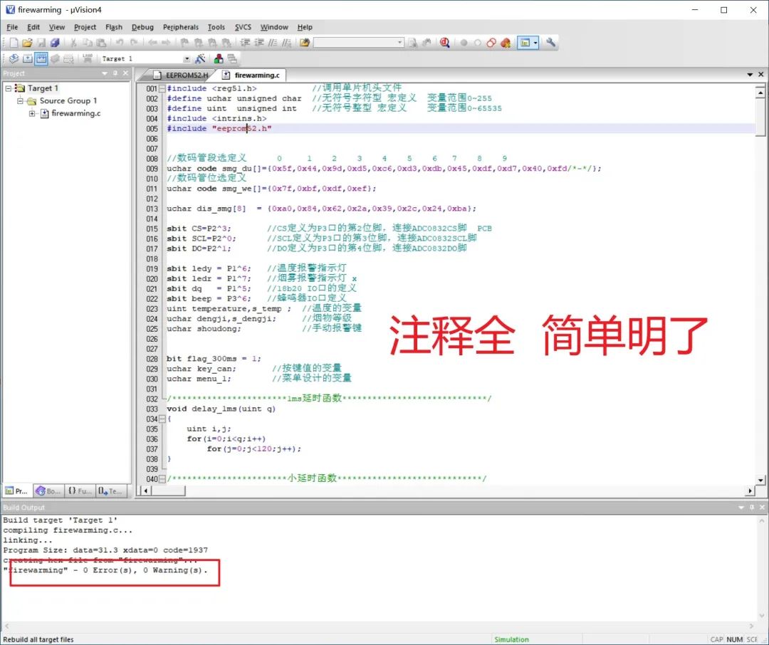
Program
Project files can be opened using Keil4/Keil5
Code
The main program flowchart is shown below.
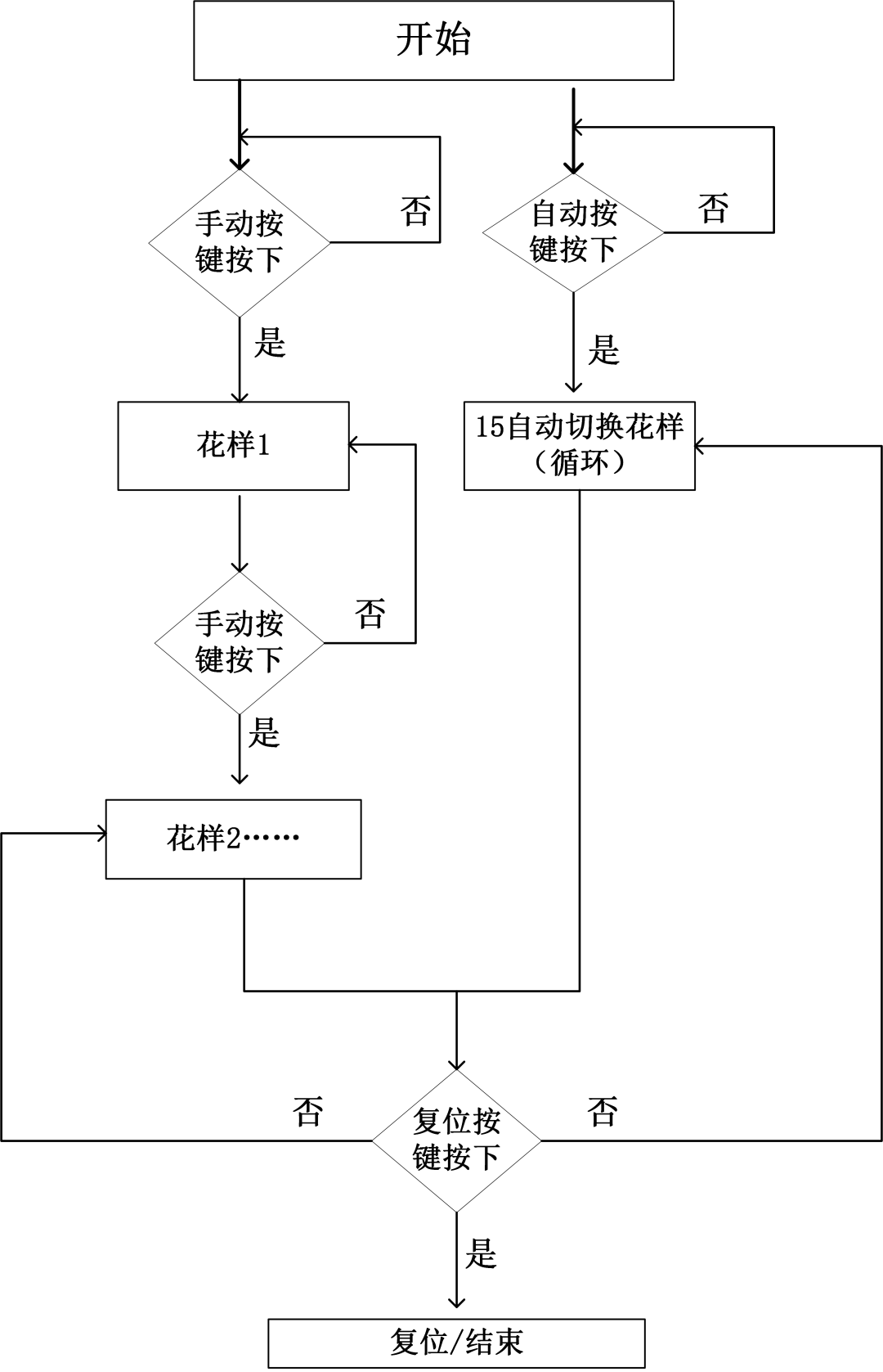
During the operation of the entire alarm system, the smoke concentration information is processed by the ADC0832, analyzed by the microcontroller to determine whether to activate the alarm. The main program also includes LED seven-segment display for concentration characters, manual alarm function, alarm concentration setting function, interrupt subroutine, etc., making the alarm function more complete and convenient.
After preheating, the program begins to execute the initialization subroutine, which sets the I/O port input and output states, initializes registers, and sets up interrupt functions. First, set the timer initial value to 50ms, using IAP to write to EEPROM as the sampling interval. Then, set timer 0, selecting mode 1. In mode 1, the timer’s working registers TH1 and TL1 are fully 16-bit participating in operations. Next, enable the timer 0 interrupt, turn on timer 0, turn off the buzzer, turn on the green light, and set the initial alarm limit.

Schematic Diagram
The schematic diagram is drawn by AD. The schematic and simulation diagram may differ; the schematic requires a power supply and a power switch module. This design document is detailed, and the hardware manual images are detailed, but we are not responsible for hardware debugging; practical implementation requires certain basic skills. The main control chip can be replaced with STC89C51/STC89C52.
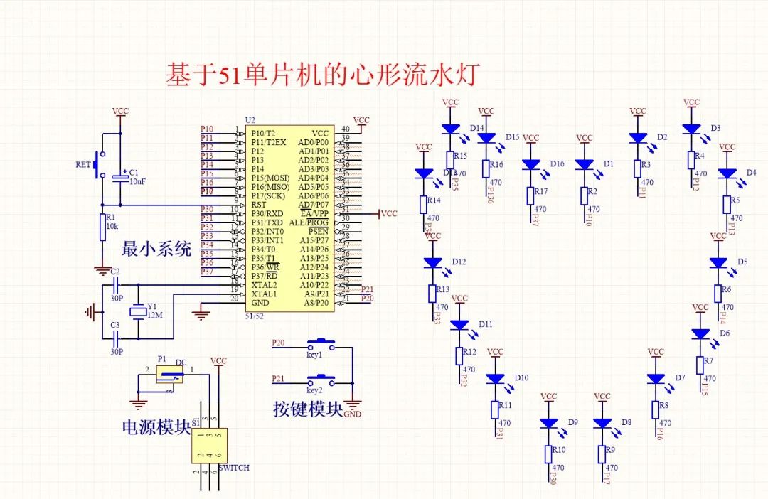
As shown in Figure 3.1, this system’s hardware design scheme is composed of the following modules:
(1) Minimum system of the microcontroller. Used to drive and control other modules to achieve overall functionality, with the STC89C51 microcontroller as the core chip, supplemented by reset and oscillator circuits.
(2) Key module. Used to implement automatic and manual modes.
(3) LED array module. Arranged in a heart shape to achieve various pattern circuits;
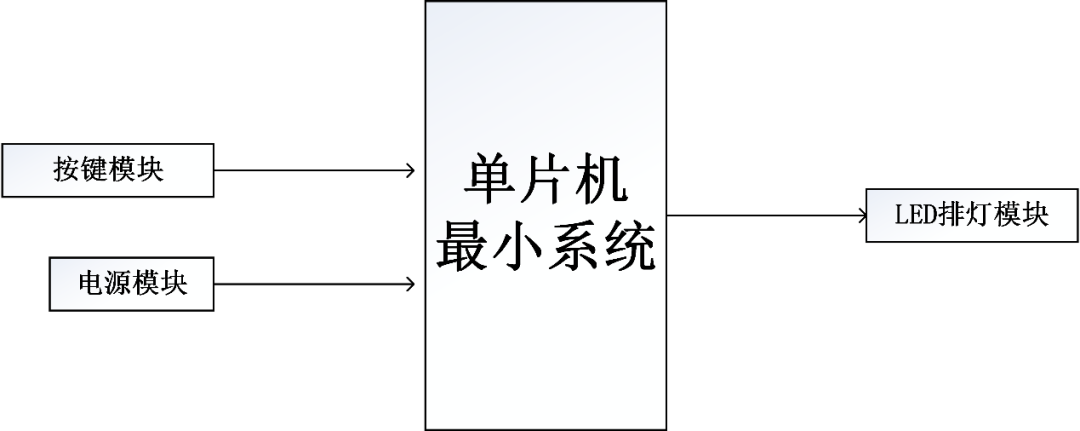
(4) Power supply module. Used for powering the entire system.

Video Explanation
Code explanation + simulation explanation + simulation demonstration + schematic explanation
-
Design Report
-
Design Background and Significance
Neon lights are the beauticians of the city, making the city exceptionally beautiful when night falls and the lights come on. The LED digital light strip adopts a new structure and proprietary technology, where the main body is connected by high-brightness light-emitting diodes (LEDs) through a special patented structure, utilizing unique optical technology and proprietary coating design. Its main features include energy saving, environmental protection, shock resistance, and waterproofing, with the greatest characteristic being uniform light emission, 360-degree light emission, and the inability to see the LED light points from the outside when in operation, completely matching the light-emitting effect of traditional neon lights. Therefore, utilizing LED light-emitting diodes to design colorful neon lights is a good choice.
This design uses the STC89C51 microcontroller’s colorful light control system to control LED colorful lights. Based on user needs, several lighting modes can be programmed, and both manual and automatic control are implemented, with different lighting times outputting control signals to turn the lights on or off at different times, driving various colors of lights to turn on or off. There are many lighting modes, allowing users to adjust the lighting frequency and time according to different occasions and times. The colorful light control system has been widely applied.
-
Design Objectives
(1) Consolidate and deepen understanding of microcontroller principles and interface technology knowledge;
(2) Cultivate the ability to select reference books and consult manuals and literature based on project needs;
(3) Learn comparative methods for scheme verification, broaden knowledge, and initially master basic engineering design methods;
(4) Master the correct use of common instruments and learn software and hardware design and debugging methods;
(5) Be able to write course design reports according to course design requirements, accurately reflect design and experimental results, and use computers to draw circuit diagrams, simulation diagrams, and flowcharts.
-
Structure Arrangement of This Article
This article revolves around the design of the LED colorful light controller based on the 51 microcontroller, starting from the demand for LED pattern lights, first clarifying the research background and significance, introducing the design objectives, and discussing the design requirements and content. The following chapters will specifically elaborate on related designs and research:
The second chapter introduces the overall system scheme and related theoretical knowledge, focusing on the system functional requirements and system scheme verification, followed by a brief introduction to the basic knowledge of system hardware and software.
The third chapter focuses on hardware system design, first clarifying the ideas and framework of hardware circuit design. It then introduces the minimum system of the microcontroller, key circuit, LED lamp circuit, power circuit, etc. Through the introduction of these key circuits, it reinforces the details and focus of hardware circuit design.
The fourth chapter elaborates on software system design, clarifying the purpose and requirements of software design through demand analysis, and further displaying the design ideas and framework through program flowcharts.
The fifth chapter introduces the steps for simulation implementation, especially the process of implementing the simulation circuit and simulation testing, perfectly realizing the design requirements and objectives.
The sixth chapter summarizes the entire article, summarizing the work and contributions made in this article, and looking forward to future research directions based on existing problems.


Material List
Next
Download
Link
Connection

Download link for this document:
https://docs.qq.com/doc/DTmZvWVZhWlRMbEVv
More resources can be found at the link below:
https://docs.qq.com/sheet/DTkhjR0t0dkhMWm5o

Contact
QQ Number|946642617
WeChat Official Account|Quality Microcontroller