This article will cover the following topics: Introduction to F1C100s, U-Boot, Linux kernel customization, and application development using C or C++. We will also provide two examples: a simple example controlling an LED blinking and another creating a GUI program with a button.
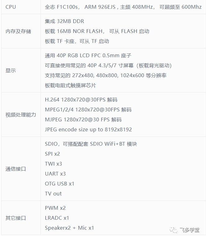
F1C100s Performance Parameters
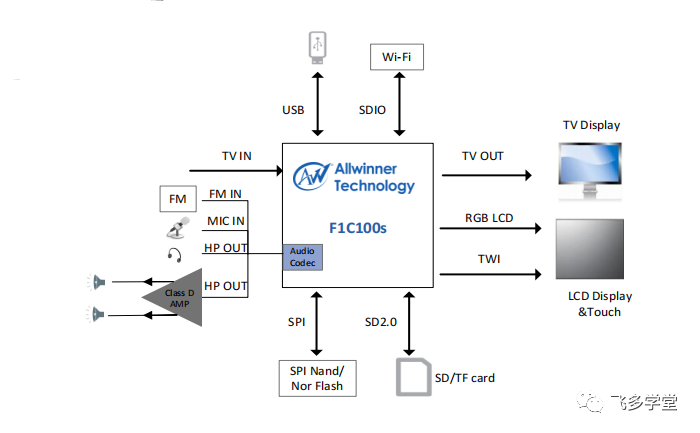
The F1C100s is a low-cost, low-power 32-bit processor commonly used in embedded systems and IoT devices. It features an ARM926EJ-S CPU architecture, 16KByte D-Cache, 32KByte I-Cache, and 32MB DDR1 SIP memory. It supports H.264 decoding at 1920×1080@30fps and MJPEG encoding at 1280×720@30fps. The F1C100s is a 720P HD multimedia processor.
The parameters of F1C100s are as follows:

USB OTG (USB On-The-Go) is a specification that allows certain Android smartphones and tablets to act as USB hosts, enabling you to connect other USB peripherals (such as keyboards or flash drives) to them. USB OTG can achieve this functionality through a single USB port. USB connections typically start from a computer (host) and link to another device, usually a peripheral such as a printer, mouse, keyboard, or USB flash drive. Devices that support USB OTG can act as either hosts or peripherals. Many Android smartphones support USB OTG, including newer Samsung phones. Some Android devices may have a USB OTG logo on the packaging or check for USB OTG information in the device settings. iOS devices do not support USB OTG, but there are ways to achieve similar functionality and connect USB devices to iPhones and iPads.
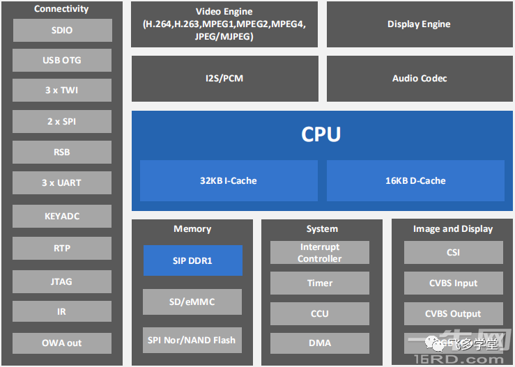
The block diagram of the F1C100S processor is as follows:
Comparison of F1C100s with other Allwinner chips:
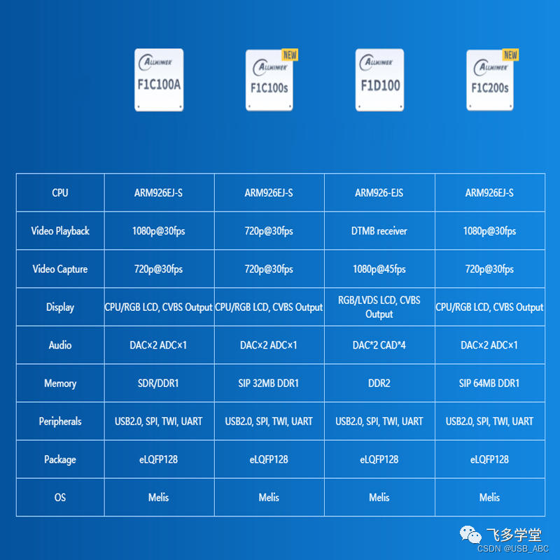
Except for memory parameters, the F1C200s has the same parameters as the F1C100s, but the F1C200s has 64M memory, while the F1C100s has 32M.
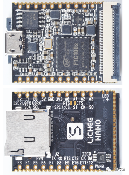
The parameters of the Lichee Pi (Lichee Pi) Nano development board are as follows:
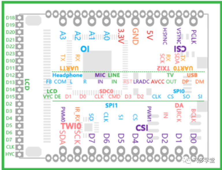
The pinout diagram of the Lichee Pi Nano development board is as follows:
This is what the Lichee Pi Nano looks like:
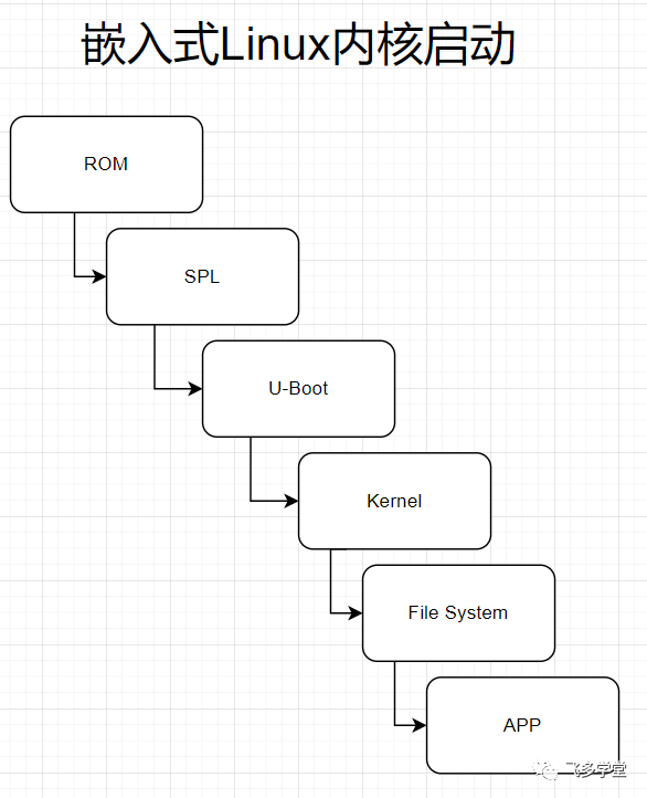
Linux Boot Process
Generally, the boot process of embedded Linux kernels can be roughly divided into five parts in order:
-
ROM
-
SPL
-
U-Boot
-
Linux Kernel
-
Root File System
-
Application
1 ROM
The first stage bootloader is located in the microcontroller‘s ROM. The ROM code is the first code block that runs automatically when the device starts or after a power-on reset (POR). The ROM bootloader code is hardcoded into the device and cannot be changed by the user.
In this article, the microcontroller refers to the F1C100s SoC chip.
The ROM code has two main functions:
-
Configuration of the microcontroller and initialization of major peripherals, such as stack setup, configuring the watchdog timer (for details, see TRM), and PLL and system clock configuration.
-
Preparing for the next bootloader by checking the boot source of the next stage bootloader (SPL) and loading the actual next stage bootloader code into memory and starting it.
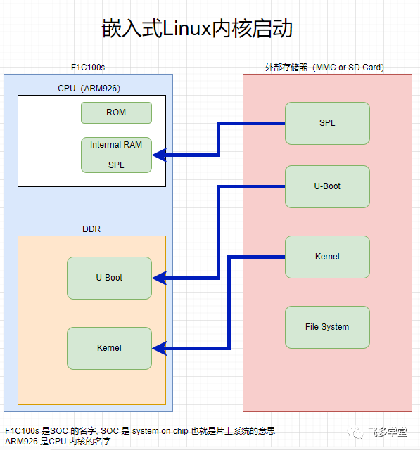
Before the device is powered on, the boot code is stored in one of two places. First, the ROM bootloader permanently resides in the CPU and cannot be modified. Second, all other parts of the boot image (SPL and U-Boot bootloader, as well as the Linux kernel and file system) are stored in non-volatile memory (such as a microSD card or eMMC). Once the device is powered on, the ROM bootloader will load the second stage bootloader (i.e., SPL) into the CPU’s internal memory. The SPL will load the third stage bootloader (i.e., the full-featured version of U-Boot) into the DDR memory inside the microcontroller. Finally, the last bootloader stage, the Linux kernel, will be pulled into DDR and executed.
2 SPL
The second stage bootloader is called SPL (Secondary Program Loader), but is sometimes referred to as MLO (MMC Loader). SPL is the first stage of U-Boot and must be loaded into internal RAM from a boot source. The configuration or user interaction of SPL is very limited, mainly used to initialize external DDR memory and set up the boot process for the next bootloader stage: U-Boot.
3 U-Boot
U-Boot allows powerful command-based control of the kernel boot environment through a serial terminal. Users can control multiple parameters such as boot parameters and kernel boot commands. Additionally, U-Boot environment variables can also be configured. These environment variables are stored in the uEnv.txt file on your storage medium or, if configured, directly in Flash-based memory. The env print, env set, and env save commands can be used to view, modify, and save these environment variables. U-Boot is also a very useful tool for programming and operating various external storage devices, as well as a powerful aid during custom board startup.
4 Linux Kernel
zImage is a compressed kernel image that contains header information describing the kernel. This header information includes target architecture, operating system, kernel size, entry point, etc. The loading of the kernel image is usually executed through scripts stored in the U-Boot environment (all scripts start with the bootcmd ENV variable and are executed after the automatic boot countdown expires or manually entered at the U-Boot prompt).
Learning history without understanding geography can only lead to half the knowledge; the same goes for learning the Linux boot sequence, as it is essential to know the location of each module:
How to Customize U-Boot
U-Boot (Universal Bootloader) is a commonly used open-source bootloader in embedded systems. Customizing U-Boot can meet specific hardware requirements and improve boot performance. Here are simple steps for customizing U-Boot on the Allwinner F1C100s, along with an example:
Step 1: Obtain U-Boot Source Code
First, obtain the version of U-Boot corresponding to F1C100s from the official U-Boot repository or Allwinner’s official resources.
git clone https://github.com/u-boot/u-boot.git
cd u-boot
git checkout -b f1c100s_branch origin/f1c100s_branch
Step 2: Configure Cross-Compilation Toolchain
Ensure that the cross-compilation toolchain suitable for F1C100s is installed. Depending on your needs, you can use the one provided by Allwinner or another applicable toolchain.
export CROSS_COMPILE=arm-linux-gnueabi-Step 3: Configure U-Boot
Enter the U-Boot source directory and use the make menu configuration tool.
make f1c100s_configThis will create a .config file containing the default configuration for F1C100s.
Step 4: Customize Configuration
Further configure U-Boot using make menuconfig to meet your specific needs. This step allows you to choose to enable or disable specific features and drivers to adapt to your hardware environment.
make menuconfigStep 5: Compile U-Boot
Use the make command to compile U-Boot.
makeAfter compilation, the u-boot.bin file will be generated, which is the customized U-Boot executable.
Example
As an example, suppose we need to output a custom welcome message during U-Boot startup. Add the following definition in the include/configs/f1c100s.h file:
#define CONFIG_SYS_EXTRA_OPTIONS "My custom welcome message!"Then recompile U-Boot:
makeFinally, flash the generated u-boot.bin to the F1C100s target device.
Linux Kernel Customization
The Linux kernel is a core component of embedded systems, and customization can adapt it to specific hardware requirements and application scenarios. Here are simple steps for customizing the F1C100s Linux kernel, along with an example:
Step 1: Obtain Linux Kernel Source Code
Obtain the version of the Linux kernel corresponding to F1C100s from Allwinner’s official or other applicable resources.
git clone https://github.com/linux-sunxi/linux-sunxi.git
cd linux-sunxi
git checkout -b f1c100s_branch sunxi-4.14
Step 2: Configure Cross-Compilation Toolchain
Ensure that the cross-compilation toolchain suitable for F1C100s is installed. This is usually provided by Allwinner or other vendors.
export CROSS_COMPILE=arm-linux-gnueabi-Step 3: Configure Linux Kernel
Use the make menu configuration tool for basic configuration.
make sunxi_defconfigThis will create a .config file containing the default configuration for F1C100s.
Step 4: Further Customize Configuration
Further configure the Linux kernel using make menuconfig to meet specific needs.
make menuconfigStep 5: Compile Linux Kernel
Use the make command to compile the Linux kernel.
make zImageAfter compilation, the generated arch/arm/boot/zImage file is the compiled kernel image.
Example
As an example, suppose we need to output a custom welcome message during the Linux kernel startup. Add the following node in the arch/arm/boot/dts/suniv-f1c100s.dts file:
dtsCopy codechosen {
    bootargs-append = " my_custom_welcome_message";
};
Then recompile the Linux kernel:
make zImageFinally, flash the generated kernel image zImage to the F1C100s target device.
Controlling LED
Next, let’s delve into how to control the blinking of an LED by writing a C program. First, we need to understand how to initialize and control GPIO.
There are many ways to control GPIO at the Linux system level:
-
Shell scripts
-
Python programming
-
C programming control.
The above lists only three common methods; there are others, as Linux has many peaks, unlike Windows.
This article will use C programming for control.
Here is a simple example, assuming we have connected an LED to GPIO0:
#include <stdio.h>
#include <wiringPi.h> // Using wiringPi library for GPIO control

#define LED_PIN 0 // Assuming LED is connected to GPIO0

int main() {
    if (wiringPiSetup() == -1) {
        printf("Failed to initialize wiringPi.\n");
        return 1;
    }

    pinMode(LED_PIN, OUTPUT); // Set GPIO0 to output mode

    while (1) {
        digitalWrite(LED_PIN, HIGH); // Turn on LED
        delay(1000); // Delay 1 second

        digitalWrite(LED_PIN, LOW); // Turn off LED
        delay(1000); // Delay 1 second
    }

    return 0;
}
This simple program uses the wiringPi library, which is a GPIO control library for Raspberry Pi and other embedded systems. In this example, we initialize wiringPi and set GPIO0 to output mode. Then, we use an infinite loop to alternate turning the LED on and off, maintaining each state for 1 second.
Simple GUI Application Example
Next, we will introduce a simple GUI program example that includes a button, which, when pressed, will pop up a message box saying “Hello World!”.
Linux GUI application development requires using GUI development libraries such as GTK or Qt. Due to space limitations, we will use GTK as an example. There is also an emerging way to develop Linux GUI applications: LVGL, which will not be covered in this article.
First, ensure that the GTK development library is installed on your system. Below is a simple example code for a GTK C program:
#include <gtk/gtk.h>

// Callback function to handle button click events
static void button_clicked(GtkWidget *widget, gpointer data) {
    GtkWidget *dialog;

    // Create a message box
    dialog = gtk_message_dialog_new(GTK_WINDOW(data),
                                    GTK_DIALOG_MODAL,
                                    GTK_MESSAGE_INFO,
                                    GTK_BUTTONS_OK,
                                    "Hello World!");

    // Run the message box and wait for user response
    gtk_dialog_run(GTK_DIALOG(dialog));

    // Close the message box
    gtk_widget_destroy(dialog);
}

int main(int argc, char *argv[]) {
    GtkWidget *window;
    GtkWidget *button;

    // Initialize GTK
    gtk_init(&argc, &argv);

    // Create main window
    window = gtk_window_new(GTK_WINDOW_TOPLEVEL);
    gtk_window_set_title(GTK_WINDOW(window), "GTK Hello World");
    gtk_container_set_border_width(GTK_CONTAINER(window), 10);

    // Create button
    button = gtk_button_new_with_label("Click Me!");

    // Add button to main window
    gtk_container_add(GTK_CONTAINER(window), button);

    // Connect button click event to callback function
    g_signal_connect(button, "clicked", G_CALLBACK(button_clicked), (gpointer)window);

    // Show all window components
    gtk_widget_show_all(window);

    // Run GTK main loop
    gtk_main();

    return 0;
}
This program first creates a main window and then adds a button to the window. By connecting the button’s click event to the callback function button_clicked, we achieve the effect of popping up a message box when the button is clicked.
Summary
This article briefly summarizes as follows:
-
Hardware Parameter Introduction:
-
The Allwinner F1C100s is a single-core processor based on the ARM926EJ-S architecture, with a maximum frequency of 900MHz.
-
It integrates various peripheral interfaces, including GPIO, UART, SPI, etc., suitable for embedded systems and IoT applications.
U-Boot and Linux Kernel Customization:
-
Using U-Boot for bootloader customization to meet specific hardware requirements and improve boot performance.
-
Utilizing Linux kernel customization tools, such as
make menuconfig, to selectively enable or disable kernel features and drivers to reduce kernel size and improve system response speed.
Upper Layer Application Development Introduction:
-
Writing applications in C or C++ to interact with the customized Linux kernel.
-
The example demonstrated controlling the blinking of an LED through GPIO, simplifying GPIO operations using the wiringPi library.
GUI Program Example:
-
Creating a simple GUI program using the GTK development library, which includes a button.
-
Triggering a callback function when the button is clicked, popping up a message box displaying “Hello World!”.
The above examples cover multiple aspects of hardware and software development, from low-level bootloaders and kernel customization to upper-layer application development and graphical interface design. These steps provide a basic framework for developing with the Allwinner F1C100s, serving as a starting point for your journey in embedded Linux. May you sprint towards poetry and the distance on this path!
Add the author’s WeChat: jiyuyun18, to discuss electronic technology.
Leave a message: Join the embedded group, if you want to join the embedded technology exchange group.