 Learn about PLC
Using the PLC’s digital output to control the inverter (i.e., connecting the PLC’s digital output directly to the inverter’s digital input, allowing the PLC to control the inverter’s start, stop, forward, reverse, and multi-speed operation at high, medium, and low speeds through programming).
Using the PLC’s analog signal to control the inverter.
The PLC controls the inverter using the RS-485 Modbus-RTU communication method.
The PLC controls the inverter using fieldbus technology.
The PLC controls the inverter using RS-485 unprotocol communication method.
Among these, the RS-485 unprotocol communication method for controlling the inverter has been widely used. In RS-485 unprotocol communication method control of the inverter, the PLC is programmed to control through RS serial communication instructions.
1. System Composition
The hardware configuration of the system includes:
1 FX2N series PLC (product version V3.00 or above);
1 FX2N-485-BD communication board (maximum communication distance 50m) or 1 FXON-485ADP + 1 FX2N-CNV-BD board (maximum communication distance 500m);
Mitsubishi inverters with RS-485 interface (F700 series, S500 series, E500 series, F500 series, A500 series), which can be used interchangeably, but the total number does not exceed 8 units.
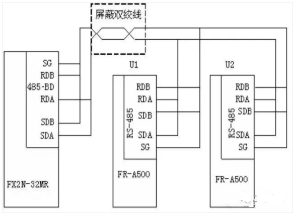
The connection between the PLC and the inverter is made using network cables, specifically connecting the RJ45 plug of the network cable to the PU socket of the inverter.
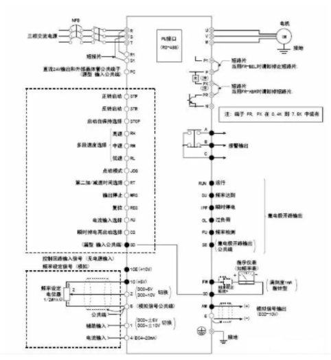
2. Mitsubishi FR-A500 Series Inverter
1. Wiring Diagram for FR-A500 Inverter Terminals
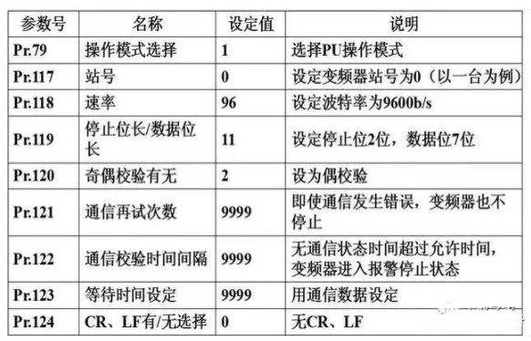
2. Communication Parameter Settings for FR-A500 Inverter
To establish communication correctly, the parameters related to communication must be set on the inverter, such as station number, baud rate, stop bit length/word length, parity, etc.
The parameters Pr.117 to Pr.124 in the inverter are used to set communication parameters.
Parameter settings can be done using the operation panel or the inverter setup software FR-SW1-SETUP-WE at the PU port.
FR-A500 Communication Parameter Settings
3. Data Format for FR-A500 Inverter
Use hexadecimal numbers; data is automatically transmitted using ASCII code between the PLC and the inverter.
1) Communication Request Data Format from PLC to Inverter
If the inverter communication parameter setting is set to no LF/CR, then the total number of ASCII characters in the communication data sent from the PLC to the inverter is 12 (in format A).
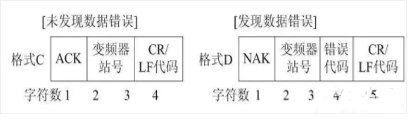
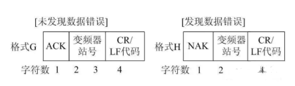
2) Input Data Format from Inverter to PLC
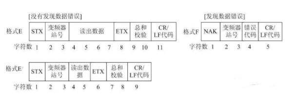
3) Response Data Format from Inverter to PLC when Reading Data
If the inverter communication parameter setting is set to no LF/CR, then the total number of ASCII characters read from the inverter is 10 (when no errors are found).
4) Sending Data Format from PLC to Inverter when Reading Data
The data in the above formats refers to the data transmitted between the PLC and the inverter (such as frequency and parameters).
The wait time is the specified time that the inverter waits between receiving data from the PLC and transmitting response data. The wait time is set according to the PLC’s response time, ranging from 0 to 150ms, with a minimum set unit of 10ms. When the Pr.123 parameter unit of the inverter is not set to 9999, the wait time is not set by communication data, and there is no wait time in the communication data format (missing one character).
The checksum is represented by the lowest byte (8 bits) of the sum (in binary) of the ASCII data being checked, expressed as two ASCII digits (hexadecimal).
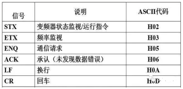
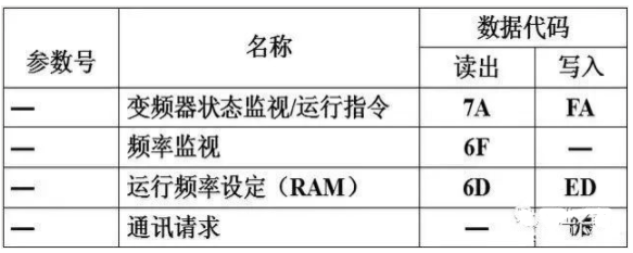
4. Control Codes and Instruction Codes for FR-A500 Inverter
FR-A500 Control Code Description
The instruction code is sent from the PLC to the inverter, indicating the program requirements (such as running, monitoring, etc.). Through the corresponding instruction code, the inverter can operate and monitor in various ways.
FR-A500 Instruction Code Description
3. Communication Program Design
1. Special Data Registers
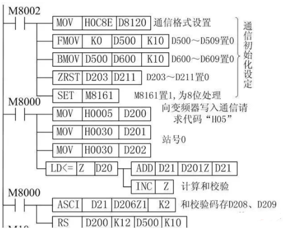
(1) D8120 sets the data communication format
Set data length to 7 bits, even parity, 2 stop bits, baud rate of 9600b/s, no header and terminator, no addition and checksum, using unprotocol communication (RS-485). Thus, D8120 is set to: b15~b0=0000 1100 1000 1110=0C8EH.
(2) D8122 stores the bytes of the current information that have not yet been sent
(3) D8123 stores the number of bytes received.
(4) D8124 is the start character (8 bits) initial value STX (02H)
(5) D8125 is the end character (8 bits) initial value EXT (03H)
(6) D8129 sets the data network timeout timer value. Its unit is 10ms
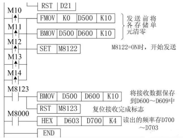
2. Communication Program
Assuming the inverter station number is 0, data length is 7 bits, even parity, 2 stop bits, baud rate of 9600b/s, no header and terminator, no addition and checksum, using unprotocol communication (RS-485).
M10 on means controlling the inverter to enter forward rotation, M11 on means controlling the inverter to stop, M12 on means controlling the inverter to enter reverse rotation, M13 on means reading the inverter’s running frequency (D700~D703), M14 on means writing the inverter’s running frequency (D400~D403).
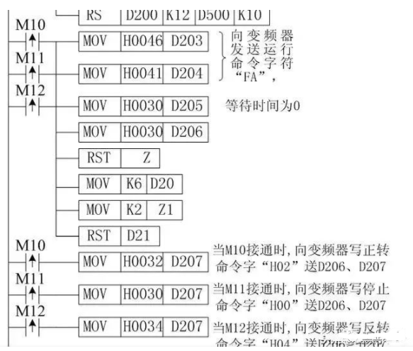
When any of M10, M11, or M12 is on, the PLC first sends a running control signal to the inverter, D200~D209 are the addresses for sending data, where D200 stores the communication request code 05H, D201, D202 store the inverter station number 0, D203, D204 store the instruction code (run command word FAH), D205 stores the wait time (0ms), D206~D207 store the sending data (D206, D207 store forward 02H/reverse 04H/stop 00H), D208~D209 store the checksum
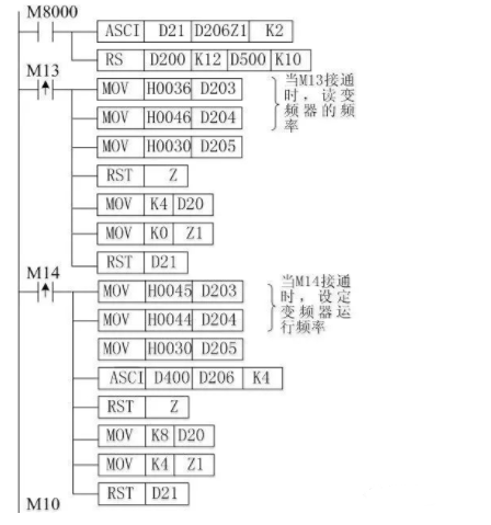
When M14 is on, the PLC sends the running frequency to the inverter. Assuming the running frequency is stored in D400~D403, D200~D211 are the addresses for sending data, where D200 stores the communication request code 05H, D201, D202 store the inverter station number 0, D203, D204 store the instruction code (write running frequency command word EDH), D205 stores the wait time (0ms), D206~D209 store the sending data (running frequency), D210~D211 store the checksum.
When M13 is on, the PLC sends a signal to the inverter to read the inverter’s running frequency. D200~D207 are the addresses for sending data, where D200 stores the communication request code 05H, D201, D202 store the inverter station number 0, D203, D204 store the instruction code (read running frequency command word 6DH), D205 stores the wait time (0ms), D206~D207 store the checksum.

D500~D509 are the addresses for received data, D600~D609 are the storage addresses for received data
Highlights
1、Illustrated Control of Industrial Robots and PLC Communication
2、Free Download: Halcon Programming Source Code (with Comments)
3、[Valuable Share] Teach You How to Calibrate Halcon
4、[Limited Time Offer] ABB Robot Training Videos + PPT Materials + Study Resources
5、[Limited Time Offer] 20 Types of Industrial Robots, Over 100 Application Case Videos
6、[Valuable Share] KUKA Robot Videos + PPT + Materials
7、[Free Download] Yaskawa + Nachi Robot Teaching Videos, Study Materials
8、[Free Gift] FANUC Robot Learning Videos + Materials
9、Siemens S7-3/400: Programming Software, Tutorials, Cases, Documentation
10、[Welfare] Free Mitsubishi FX5U Learning Materials
11、Is Debugging Industrial Robots Difficult?
12、Ten Common Algorithms for Learning Artificial Intelligence Technology
13、Wireless Serial Communication (Free Port) between S7-1200 and Other PLC/Configuration Software
14、There has never been a job called: High Pay, Less Work, Close to Home, High Position, Low Responsibility!
15、FANUC Robot Palletizing Programming Detailed Explanation
Source: Comprehensive Network, contact for deletion if infringing.