
Introduction
All STM32 series products come with a CRC peripheral that provides hardware support for CRC calculations, saving code space for applications. The CRC checksum can be used to verify the correctness of data during transmission and can also be used for integrity checks during data storage. In IEC60335, CRC checks are accepted for verifying the integrity of FLASH. In applications requiring integrity checks of FLASH, the CRC checksum for the entire FLASH must be calculated beforehand (excluding the byte that stores the final CRC value) and placed at the end of FLASH. During program startup or execution, the CRC checksum for the entire FLASH is recalculated using the same method and compared with the CRC value stored at the end of FLASH.
Since version 5.5, EWARM has supported CRC calculations for STM32 chips. The process of calculating the entire FLASH’s CRC checksum and storing it at the end of FLASH can be done in IAR. By configuring EWARM’s CRC calculation parameters, the entire FLASH space can be automatically CRC-calculated, and the result will be placed at the end of FLASH. This article will introduce how to configure the CRC parameters in IAR to ensure they are consistent with the STM32 CRC hardware module. The examples in this article are based on STM32F072.
The calculation of the CRC checksum for the STM32’s CRC peripheral uses polynomial division, which can be implemented using XOR operations between the divisor and the dividend. This method is very suitable for implementation via hardware circuits. When using the STM32 CRC peripheral, considerations include: which CRC generation polynomial to use, the input data (the data to be verified), and the initial value.
1. The default generation polynomial uses the CRC32 polynomial: 0x4C11DB7

Some chips support programmable polynomials, such as STM32F3, STM32F0, STM32L0
2. Initial Value: The default initial value for STM32’s CRC is 0xFFFFFFFF. The STM32F3, STM32F0, and STM32L0 series can modify the initial value.
3. Input/Output Data Reversal: The STM32F3, STM32F0, and STM32L0 series also provide functionality for reversing input/output data. By default, input and output data are not bit-reversed.
· Bit reversal of input data can be set to operate by byte/half-word/word. For example, if the input data is 0x1A2B3C4D, o Each byte is reversed bit by bit, resulting in 0x58D43CB2 o Each half-word is reversed bit by bit, resulting in 0xD458B23C o Each word is reversed bit by bit, resulting in 0xB23CD458· For output data reversal. o For example, if the output data is 0x11223344, the reversed result is 0x22CC4488
CRC Configuration in IAR
1. Modify the Link File to specify the storage location of the checksum in FLASH, add the following statement to the Link file.

This statement specifies that the CRC value is placed at the end of FLASH. It is the end of the entire FLASH space, not the end of the application code. Thus, the CRC value’s position is fixed and does not change with the size of the code.
2. Configure Parameters on the Checksum Page
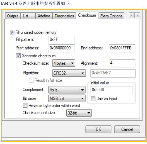
Description of the IAR Checksum page (v6.4 and above)
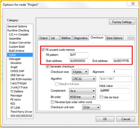
The IAR checksum page is divided into two parts. The first part, outlined in red, defines the range of FLASH that needs CRC calculation and the fill value for free bytes. The remaining part is for setting the checksum calculation parameters. Checksum size: Choose the size of the checksum (in bytes) Alignment: Specify the alignment of the checksum. If left blank, it defaults to 2-byte alignment.
Algorithm: Select the checksum algorithm Complement: Whether to perform complement calculation. Selecting “Asis” means no complement calculation. Bit order: The order of bit output. MSB first, with the high bit of each byte in front. LSB first, with the low bit of each byte in front. Reverse byte order within word: Reverse the order of bytes within a word for input data. Initial value: The initialization value for checksum calculation Checksum unit size: Select the unit size for iteration, iterating by 8-bit, 16-bit, or 32-bit.
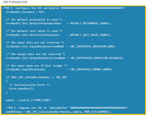
3. Default Configuration of IAR for STM32 CRC PeripheralConfiguration of STM32 CRC peripheral:
POLY= 0x4C11DB7 (CRC32) Initial_Crc = 0Xffffffff Input/Output data not reversed Input data: 0x08000000~0x0801FFFB. (The last 4 bytes are used to store the calculated CRC value)
In practical use, we can configure as needed based on the actual application requirements.
=================================
Previous Topics Links:
1、STM32 Supply Statement!!
2、Unexpected HSE_RDY Set When No External High-Speed Clock
3、A Case of a Crash Caused by Using External SRAM
4、Leakage Current Analysis in STOP2 Mode of STM32L4
5、Ways and Means to Obtain ST MCU Technical Materials and Related Support