Table of Contents
1. Why Flash Loader
2. Flash Loader Design Details
2.1 Simple Code Framework
2.2 Fascinating Macro Usage
2.3 Key Configuration Files
3. dmac and mac Files
4. Summary
To develop domestically produced automotive chips, IAR is an essential integrated tool for compilation and debugging. The historical background is not elaborated here; today, we mainly discuss the key points of Flash Loader design based on IAR.
1. Why Flash Loader
Most MCUs come with eFlash. If you want to debug based on Flash, it is not feasible to erase and write Flash directly through the Debug port, because the Flash IP varies by chip manufacturer, and the controllers and command sequences are also different;
Therefore, a small segment of custom driver software based on each chip’s Flash is needed to implement code flashing. This program is the Flash Loader, which is logically similar to the Bootloader of an automotive ECU. Here, IAR acts as the host computer, so the Flash Loader must meet some customization requirements of IAR.
If interested, you can read IAR’s documentation on Flash Loader, titled “Flash Loader Development Guide“.
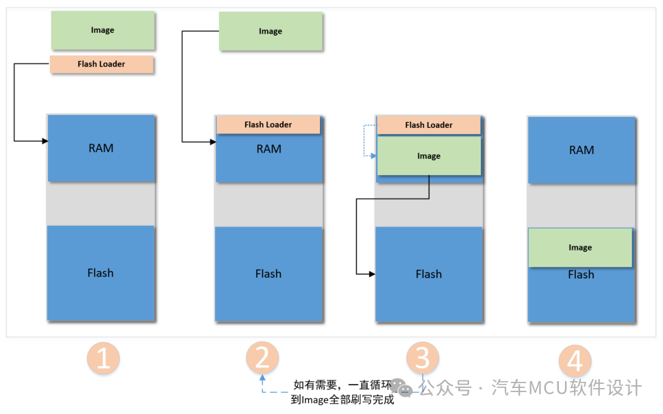
The specific process can be summarized as follows:
-
The IAR Debugger component C-SPY first downloads the Flash Loader to the target board’s RAM, with the remaining RAM used as a buffer to store the image file.
-
The image is downloaded to the RAM buffer; the Flash Loader calls the relevant drivers to flash the image to Flash until all images are written into Flash;
-
C-SPY clears the RAM, points the PC to the user program entry, sets the SP, and begins debugging.
2. Flash Loader Design Details
2.1 Simple Code Framework
IAR provides template files for Flash Loader, located at: IAR Systems\arm\src\flashloader\framework2, mainly including the following six files:
-
flash_config.h: Configuration file for Flash Loader, used to set parameters for C-SPY and driver functions;
-
flash_loader_extra.h: Additional framework declarations, but not much focus on it;
-
flash_loader_asm.s: Startup source code based on the MCU core, which requires almost no major modifications; the only point to note is the SP setting;
-
flash_loader.c: Contains the framework code, which cannot be modified;
-
flash_loader.h: Framework prototype declarations;
-
flash_loader_ram.c: The file where specific drivers need to be added.
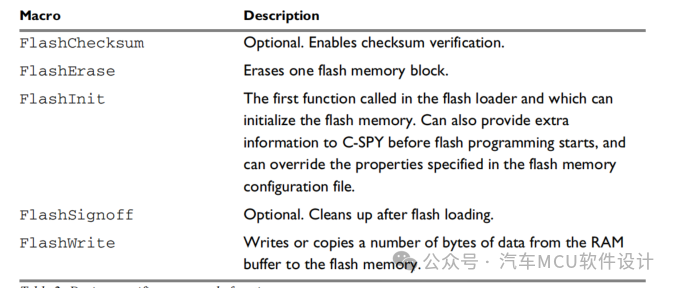
The framework is set up in flash_loader_ram.c, and the specific function interfaces are shown in the table below:
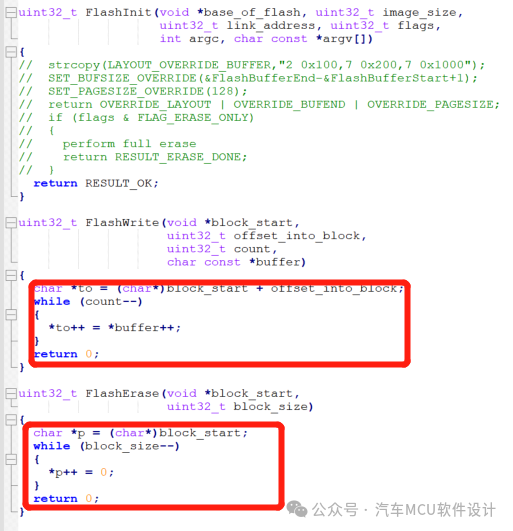
The source code is as follows:
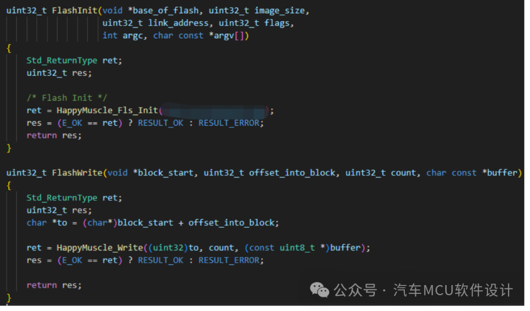
Clearly, the method of erasing code implementation for Flash is not advisable, so what we need to do is implement the driver based on the specific MCU in the above functions. If the chip manufacturer has already encapsulated the interface, it can be directly utilized. As shown below:
2.2 Fascinating Macro Usage
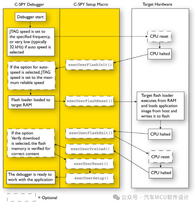
The code framework does not seem complicated, but if we encounter situations where flash or optionByte is protected by default, we need to do some preliminary work. IAR provides the Macro feature to link C-SPY and the target hardware. We take the Debug in Flash process as an example:
Image source: IAR C-SPY® Debugging Guide
During the connection of C-SPY with the target MCU and the downloading of code, the above macros can be executed to achieve the desired functionality. For example, after C-SPY downloads the Flash Loader to RAM, it can immediately execute execUserFlashReset(), where we can add any code according to the syntax. After execution, C-SPY sets the PC to the Flash Loader entry and starts the function of erasing Flash. The usage of other macros follows suit.
Familiarity with this process is essential when designing a Flash Loader to ensure that each Macro functions at the appropriate time.
2.3 Key Configuration Files
So far, we have discussed processes, but we have not yet addressed the most critical areas: How does C-SPY know the address mapping space for flashing Flash? Where are the above macros defined? Where is the compiled Flash Loader placed?
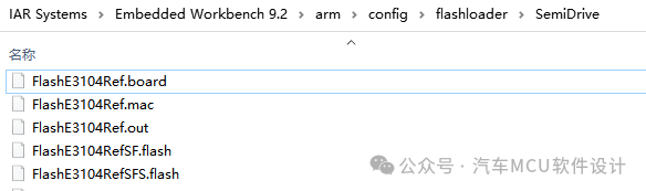
Let’s take a look at the configuration file for the Flash Loader of the Xinshi E3104, located at:
-
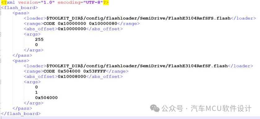
.board file, in XML format, is the configuration file for the Flash memory system, which tells IAR the Flash-related properties of the target board. It looks like this:
-
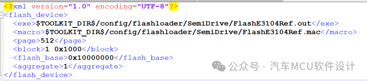
.flash file, also in XML format, informs IAR of the path to the Flash Loader program, the base address of the flash memory, flash memory page, block size, etc. A single board file can contain multiple .flash files, allowing multiple images to be flashed at once;
-
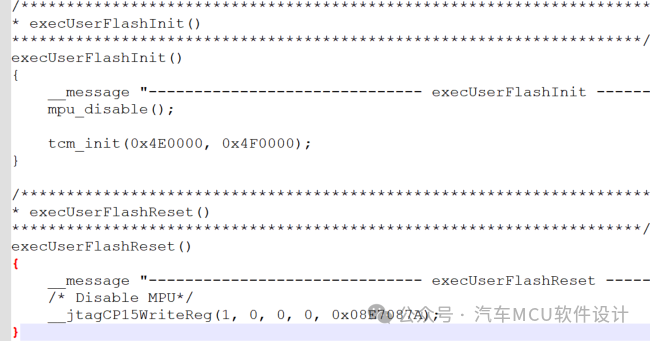
.mac file, contains auxiliary macros, which are various functions like those in the previous images, as shown below:
So what is the .out file for? It is the product of the compiled Flash Loader project.
If you are interested, you can look at the source code of NXP, Infineon, GD, and other flash loaders in the path \arm\src\flashloader.
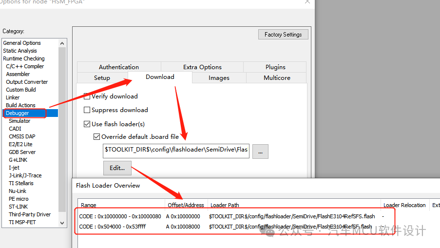
Finally, to use the Flash Loader in the debugging interface, click Project->Option->Debugger, select the target .board file to load the Flash-related information;
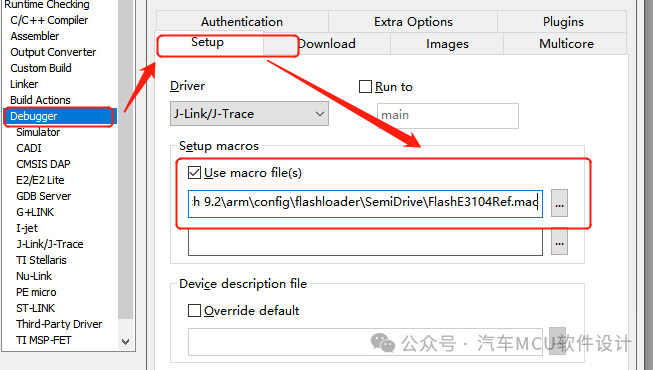
Click Debugger->Setup, and select the .mac file.
3. dmac and mac Files
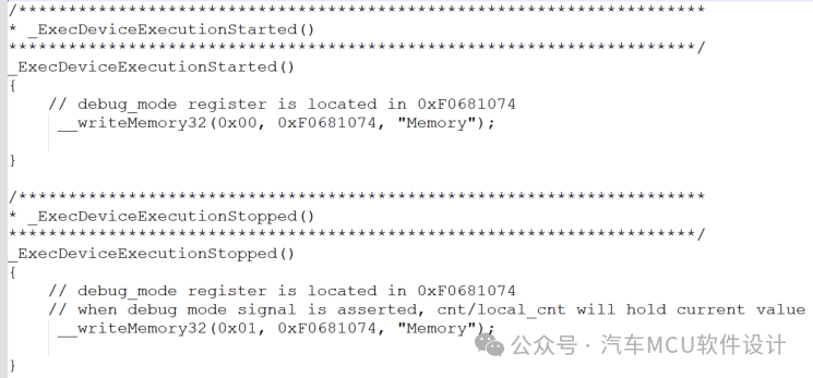
One point that can easily be confused is that there is a dmac file in the Debugger folder under the installation directory, which does not need to be manually loaded in the debugging interface; it will automatically be called during the entire debugging process. We commonly use it to toggle the MPU, operate the watchdog, etc., as shown below:
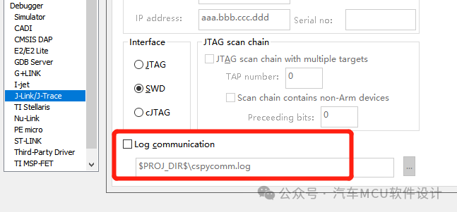
In fact, when running the Flash Loader, the functions in the dmac file will also be called. Therefore, when designing functions in the mac file, we also need to refer to the content already implemented in the dmac. We can open the corresponding hardware’s debugging log system to observe the function call order between mac and dmac.
4. Summary
At this point, the design thought of the Flash Loader based on IAR has been sorted out. The remaining task is to start receiving various debugging bugs. That’s it!
Previous Reviews:
1. Selected Automotive Calibration
Automotive Calibration Technology – Detailed Explanation of Calibration Concepts
Automotive Calibration Technology – The Past and Present of Bypass
Long Article: Automotive Calibration Technology – Overview of XCP
2. AUTOSAR Selected
AUTOSAR CryptoStack – What Private Goods Are Included in CSM Job
AUTOSAR Diagnostic Stack Analysis (Part 1)
AUTOSAR OS Overview (Part 1)
3. Automotive Cybersecurity Selected
Automotive Information Security – Common Password Algorithms for MCU Startup
Analysis of Automotive Cybersecurity Solution Requirements
Automotive Information Security – Common Automotive MCU Secure Startup Solutions
Overview of In-Vehicle Information Security Scenarios
4. Automotive Functional Safety Selected
TC3xx Startup Functional Safety Mechanism Analysis
TC3xx SMU, PMIC, and Transceiver Functional Safety Closed-Loop Concept
5. Automotive Virtualization Selected
Automotive ECU Virtualization Technology Exploration (Part 1)
Automotive ECU Virtualization Technology (Part 2) – U2A Virtualization Function
6. Miscellaneous
Flash Simulation EEPROM Principle Analysis
The Long Journey: The Story of Domestic Substitution of Automotive MCU
Automotive MCU Application Scenarios and Progress of Domestic Substitution