1. Overview
This article is aimed at beginners who have not yet encountered Keil. If you are a seasoned professional, you may skip this section. To get started quickly, many details and explanations will be omitted; for an understanding of the principles, please refer to the advanced section.
2. Software Introduction
Keil provides a complete development solution including a C compiler, macro assembler, linker, library management, and a powerful simulation debugger, all integrated into a development environment (μVision).
The software currently has poor support for Chinese, and it is not recommended to install any Chinese language packs found online. Additionally, avoid using Chinese characters in the project file paths, as this may lead to unexpected issues.
Demo Version: 5.24a
3. Terminology
IDE: Integrated Development Environment, which refers to a comprehensive environment for development, typically including a code editor, compiler, debugger, and graphical user interface tools. For embedded development, you first need an editor to write code, followed by a compiler to convert the code into machine-executable code, and sometimes a debugger is needed for debugging on the corresponding hardware chip. To facilitate operations, these tools are usually integrated into a single application, known as an IDE. The Keil uVision discussed in this article is one such IDE.
Keil: Keil is actually the name of a company, and the software developed under its name starts with Keil. Current versions include Keil MDK-ARM, Keil C51, Keil C166, and Keil C251.
uVision: uVision is the integrated development environment (IDE) developed by Keil, which allows for code editing, file management, and program compilation and debugging.
MDK, C51: If you want to develop ARM core chips, you need to install MDK-ARM; if you want to develop 51 core chips, you need to install C51. In other words, MDK and C51 are different development environments that Keil has developed for different chip cores.
CMSIS: ARM Cortex™ Microcontroller Software Interface Standard (CMSIS) is a vendor-independent hardware abstraction layer for the Cortex-M processor series.
Flashing: Flashing software is just a term that originated from the earliest CD burning, where data was burned onto a disc using a laser, leading to the irreversible recording method being referred to as flashing.
bin File: A binary file, the use of which depends on the system or application. It is an abbreviation for the file format binary. A file with the extension “.bin” simply indicates that it is in binary format. Generally, it is machine code, the result of compiling assembly language.
axf File: The axf file format is used by ARM chips, and it contains not only the bin code but also debugging information output to the debugger, such as the line numbers corresponding to each line of C code.
Hex File: Intel HEX files are ASCII text files made up of lines that conform to the Intel HEX file format. Each line in an Intel HEX file contains a HEX record, which consists of hexadecimal encoded numbers corresponding to machine language code and/or constant data. Intel HEX files are typically used to transfer programs and data that will be stored in ROM or EPROM.
4. Download Link
You can download directly from the official website and generate a license using a key generator. It is fine for personal use, but for corporate use, it is recommended to purchase a legitimate version, otherwise, you might get caught (you may receive email warnings sent to the company CEO, don’t ask me how I know).
5. Software Usage
1. Software Installation
There is nothing special about this; just click next all the way. If it’s for personal use, it’s generally not recommended to install it on the C drive, as subsequent chip packages will default to this directory, making the files very large.
2. Download/Install Chip Packages
Unlike previous versions of Keil, where chip packages were integrated into the software, meaning that once you installed Keil, you could choose from corresponding chips. However, as the number of supported chips has increased, the software size has become larger. If all chip packages were bundled with the software for download, it would likely exceed hundreds of GB. Therefore, to simplify, Keil has separated the integrated environment from chip packages and example routines, which must be downloaded separately as needed.
– Download in Keil
Click on “Pack Installer”, which is this icon  . The first time you open it, it may be slow because it needs to automatically update all chip package information from the official website. A tricky point here is that if you do not update, you may not find the chip you want, so you have to wait for the information to update. However, the foreign link may occasionally disconnect.
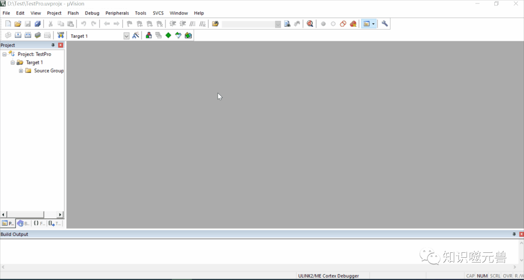
After the update, find the chip model you want to install in the left window, you can choose the entire series (or a specific chip, the result is the same). Here we take STM32G071 as an example. Then in the right window, find “Device Specific” and click on “Keil:STM32G0xx_DFP” to install it. (Again, the download can be very slow when the network is poor, and it often disconnects).
Once the installation is complete (the progress bar is in the bottom right corner), the “Install” button will change to “up to date”, indicating that the installation was successful.
– Download from the Official Website
The previous method often does not work, either due to poor network conditions or other issues. Therefore, you can use another method to update chip packages, which is to download the chip packages in advance from the official website and then click to install.
Official website link: https://www.keil.com/dd2/Pack/
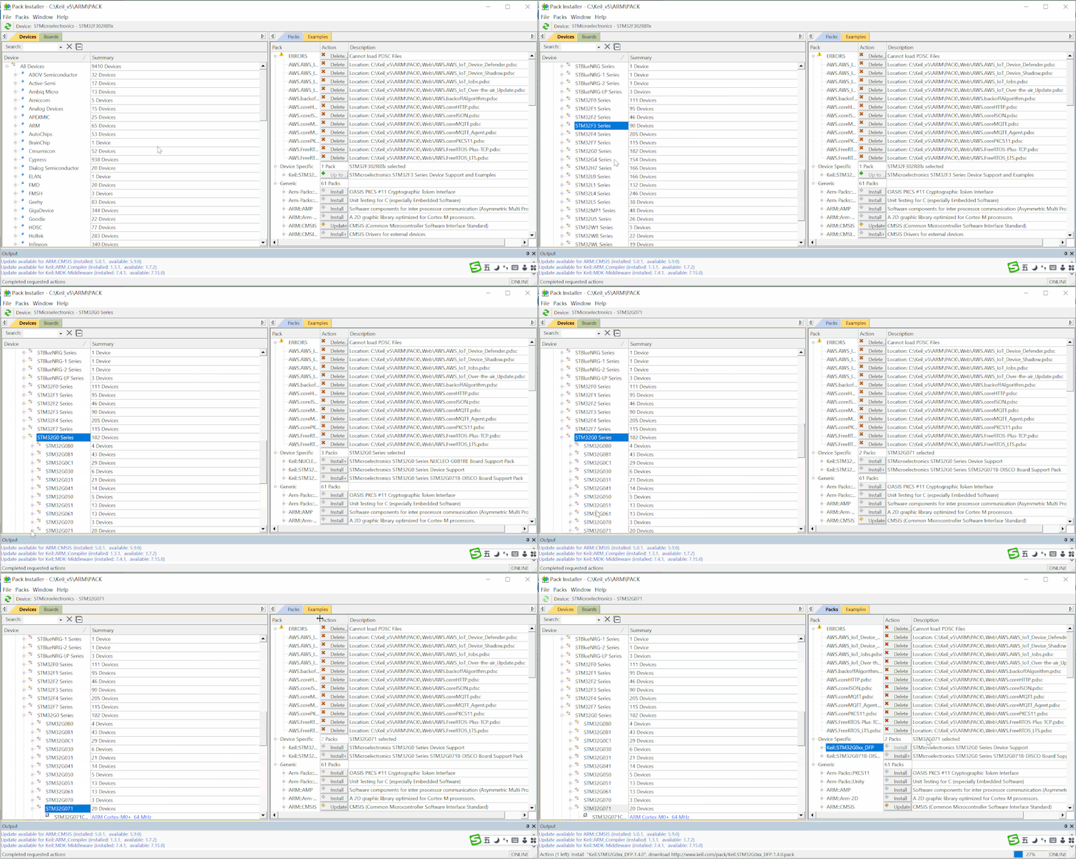
Similarly, find the corresponding chip package, select the corresponding version; the top one is the latest release. Click Download to download.
This method has the advantage that even if you cannot download from the official website, you can use someone else’s help to download it. To prevent friends from encountering network interruptions while downloading from the official website, here are some commonly used chip packages for the STM32 series for download (the version may not be the latest, but should suffice).
3. Create a New Project
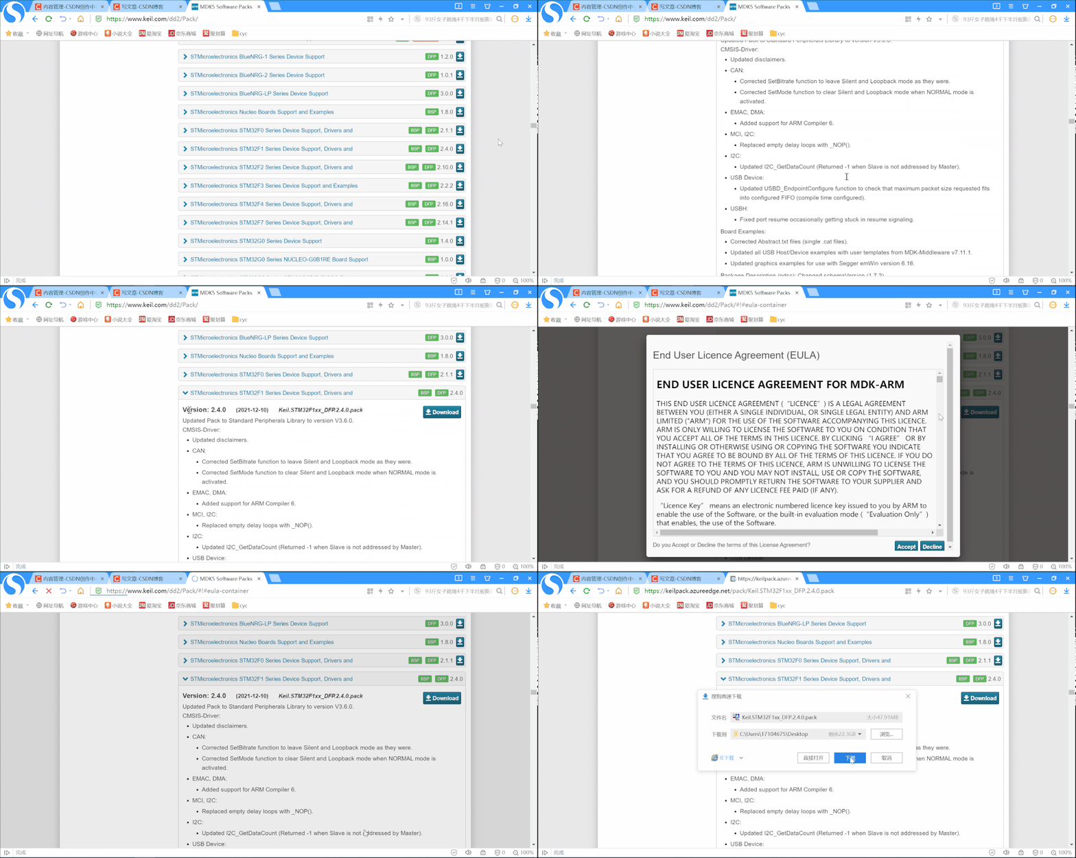
Click “Project” -> “New Project” to create a new project, select the path to save the project in the pop-up window, set the project name, and click save. Since this is a new project, the software will automatically pop up a chip selection box for you to choose the microcontroller model you are currently using; here we select STM32G071RBTx, and then choose the interface standard, which we will select CMSIS.
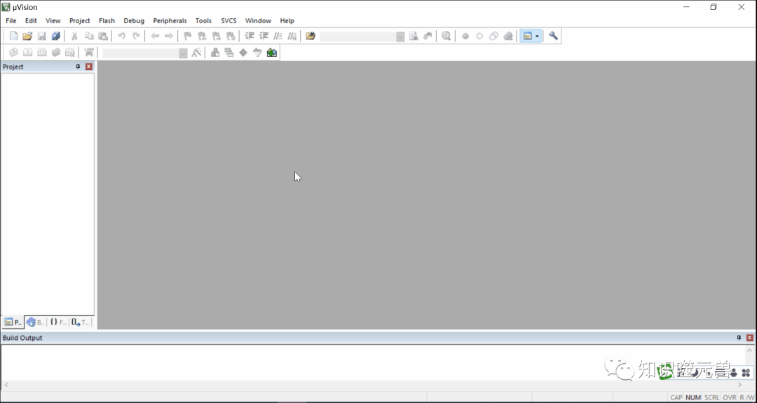
After completing the above steps, a simple project has been created. Due to time constraints, we used the superpower—STM32CubeMX to configure and generate a project. This includes the initialization of the debug port and the initialization of a GPIO port, specifically the PA5 port used for the LED light.
4. Create/Add Files
Having a project is not enough; it’s like building a house; at this point, you’ve only laid the foundation. To make it livable, you need to add some core components, which are our source code.
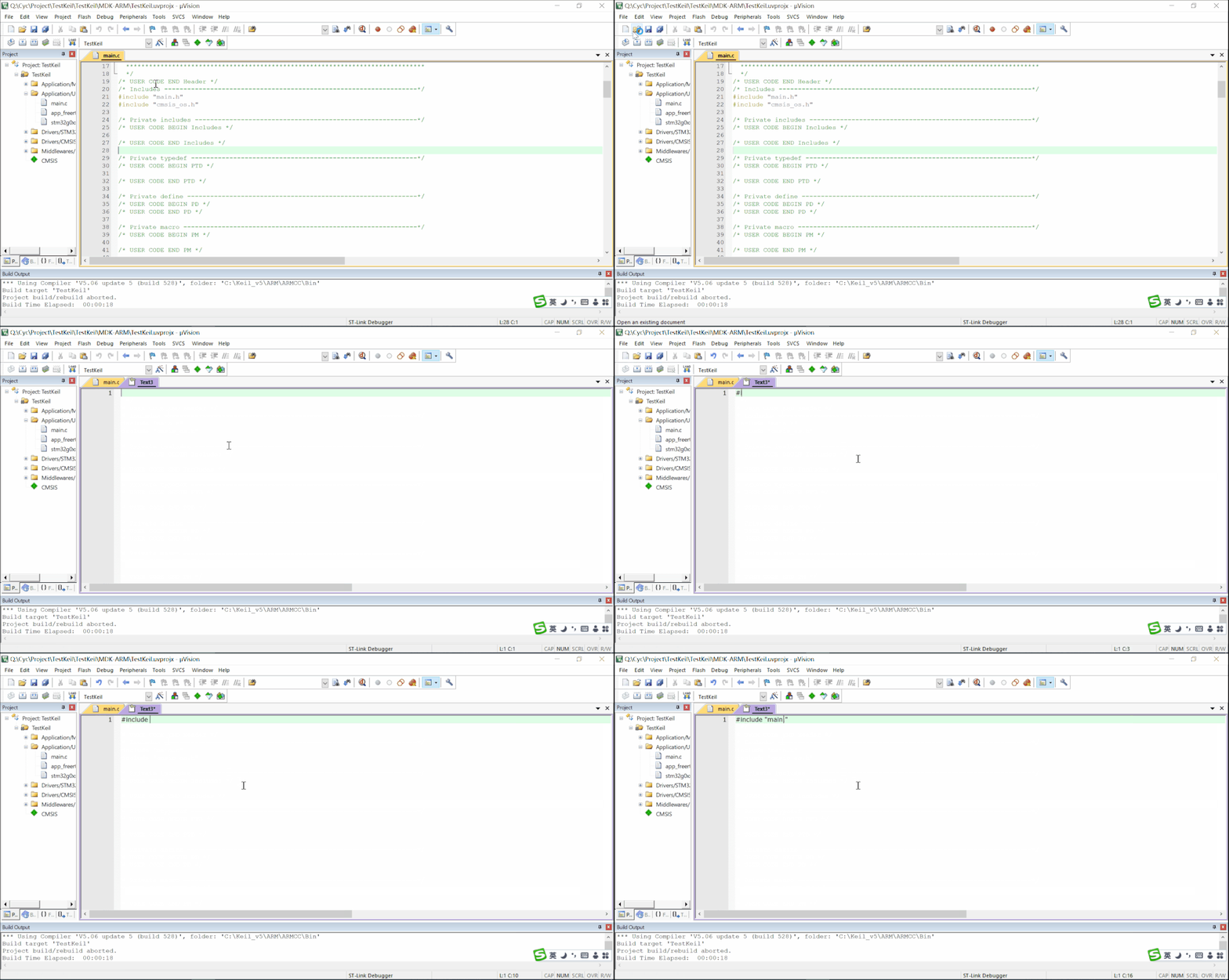
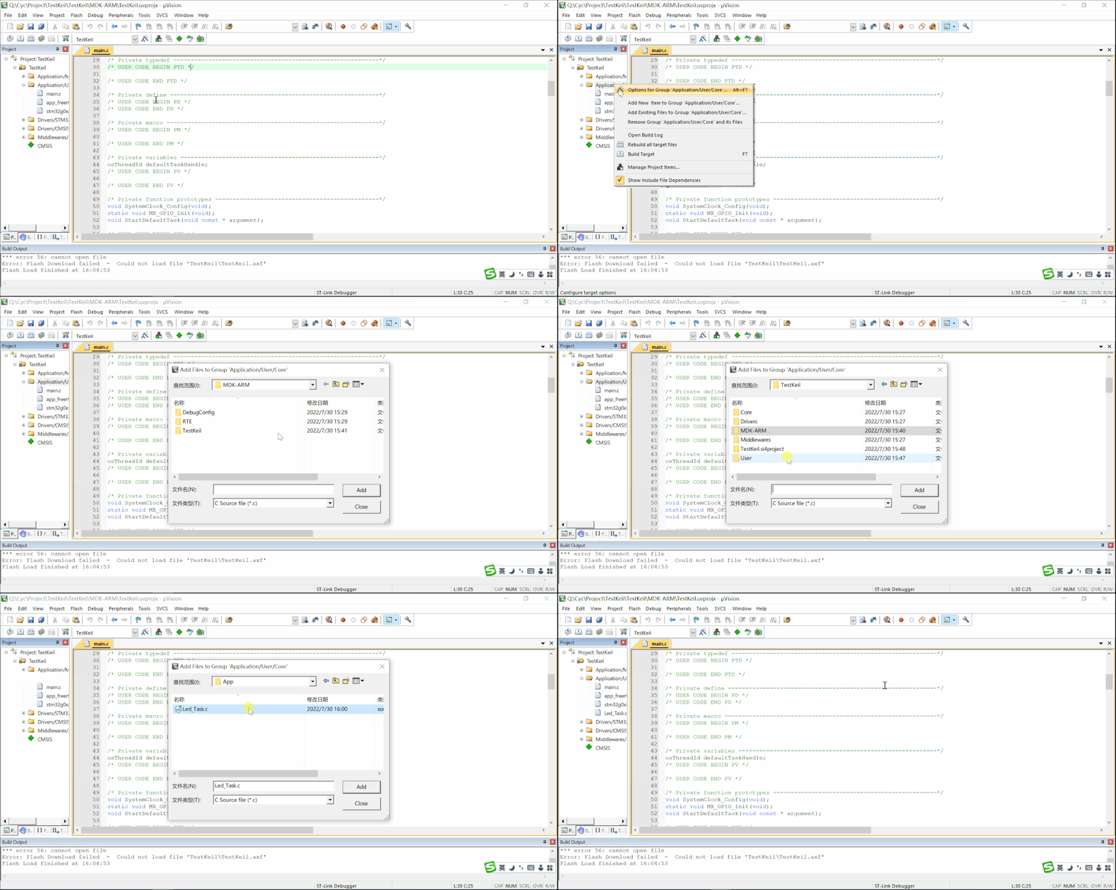
Since this demonstration uses a project generated by STM32CubeMX, some initialization code files have already been added. What we need to do now is add the logic file for the LED blinking. Due to time constraints, the blinking code file and logic are already prepared.
5. Configure the Project
To ensure proper matching with the development board and programmer, we also need to configure the project.
– Include Header File Paths
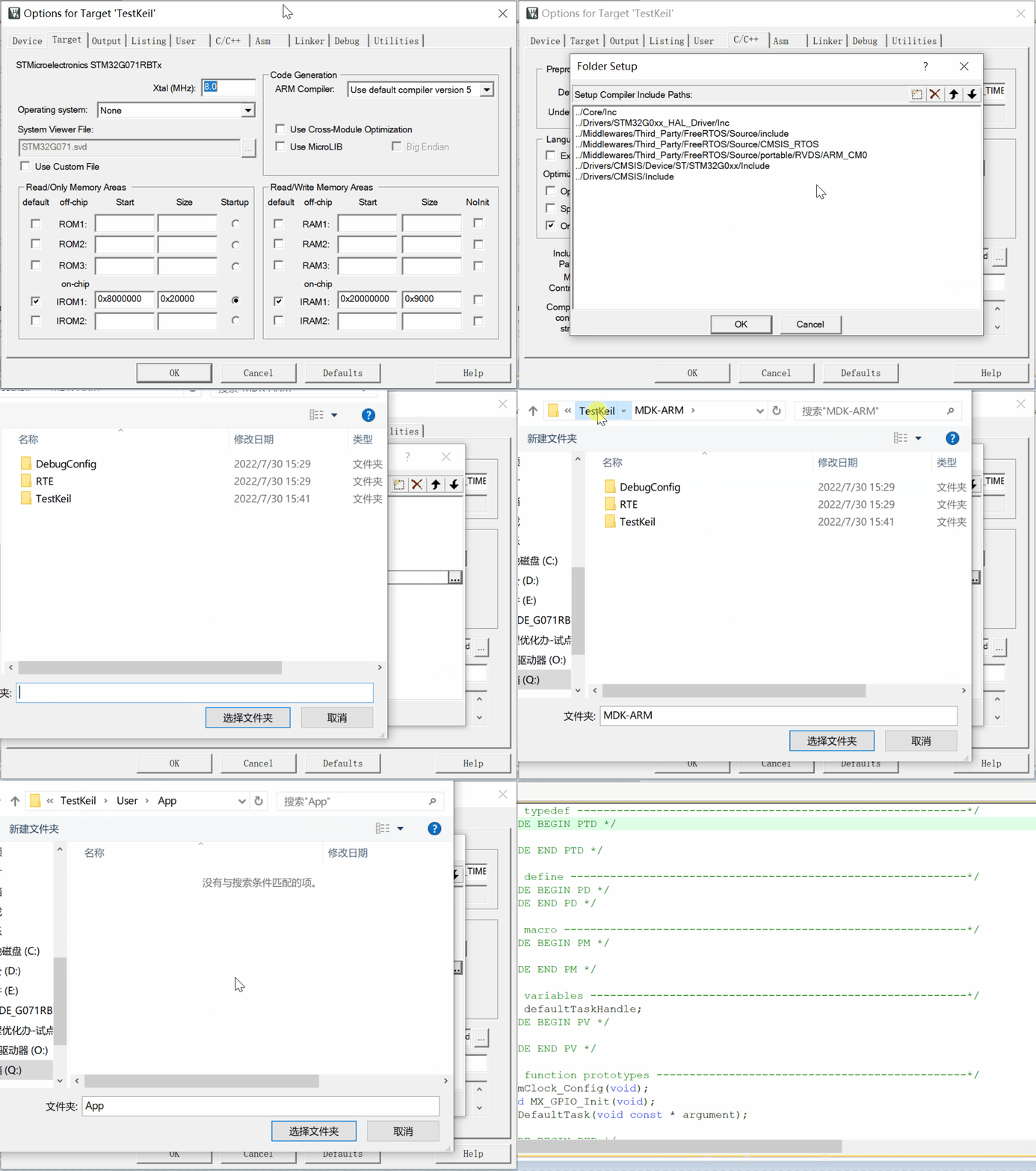
Previously, only the necessary core code files were added, and these files are still managed separately. Although there may be references to file B in file A (using include), the Keil software does not know where to find files A and B, so we need to inform it of each file’s path. Since .c files are directly added to the project, their paths are already included, but for .h files, the software does not know where they are, so we need to manually add the path where the .h files are located.
– Select Programmer
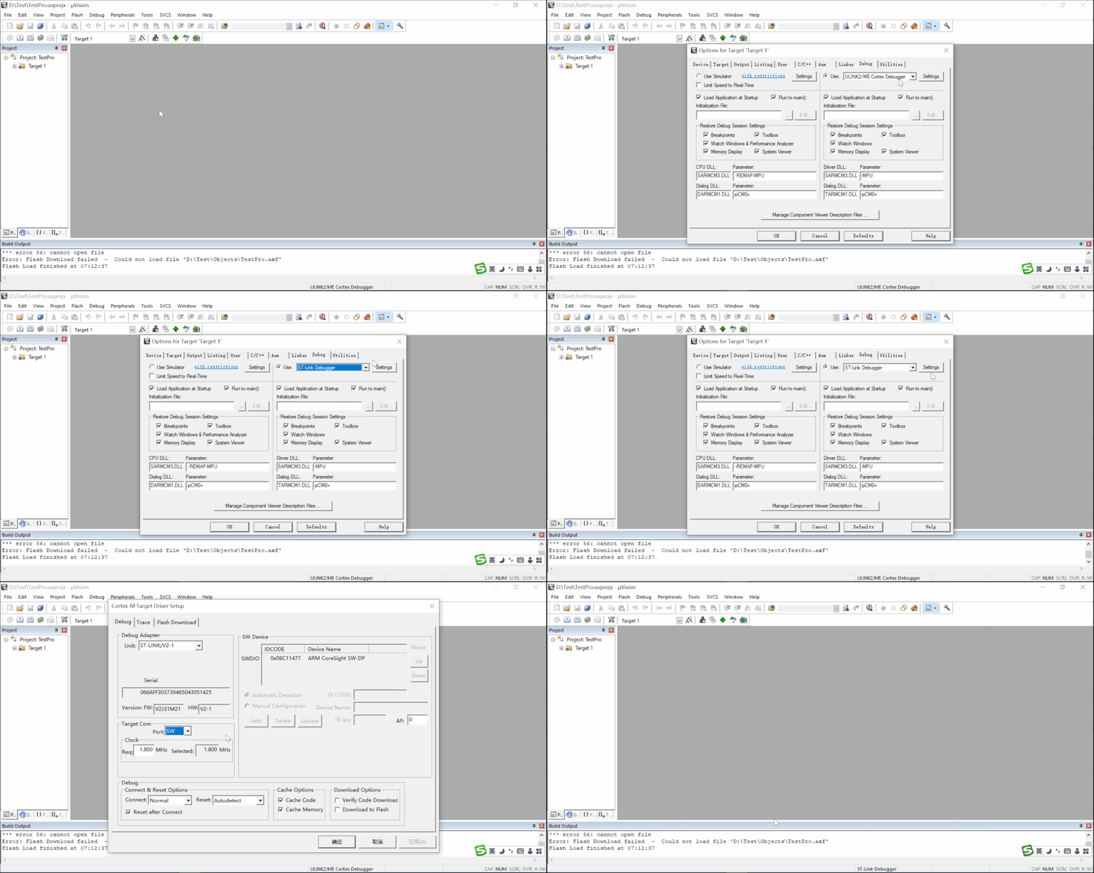
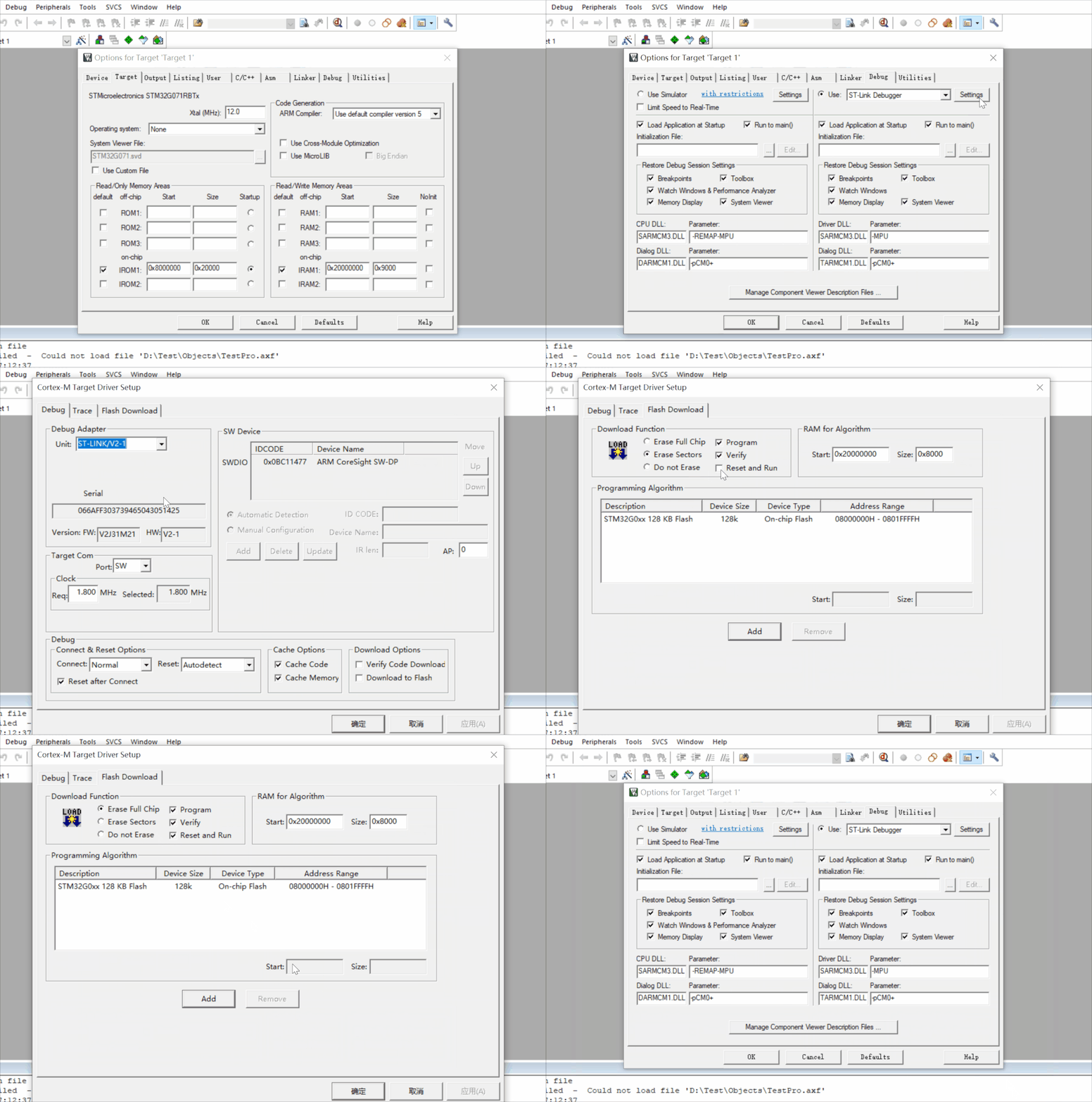
You can choose between online debugging or offline simulation. If you have a development board, it is recommended to select online debugging to experiment directly on the board. After selecting online debugging, you need to choose the type of programmer; here we select ST-Link, the type of programmer that comes with the development board.
– Generate Hex
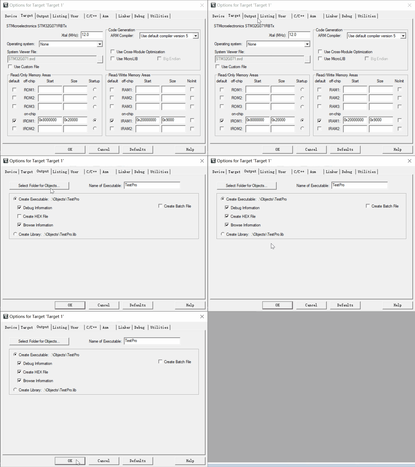
In some cases, flashing can only be done through Hex files, so you need to check “Create HEX File” in the project settings; this will automatically generate an executable Hex file after compilation.
– Select Reset After Flashing
Selecting “Reset and Run” allows the program to run immediately after flashing; otherwise, you may notice that the program does not run until you manually reset it. To avoid strange issues, it is recommended to check “Erase Full Chip”.
6. Compile
After adding files and configuring the project, we can click compile. The software will automatically call the compiler, linker, etc., step by step converting the source code (.c and .h files) into a machine-recognizable .axf file (which contains binary machine code and some debugging information). If “Generate Hex” is checked, it will also generate a hexadecimal .Hex executable file.
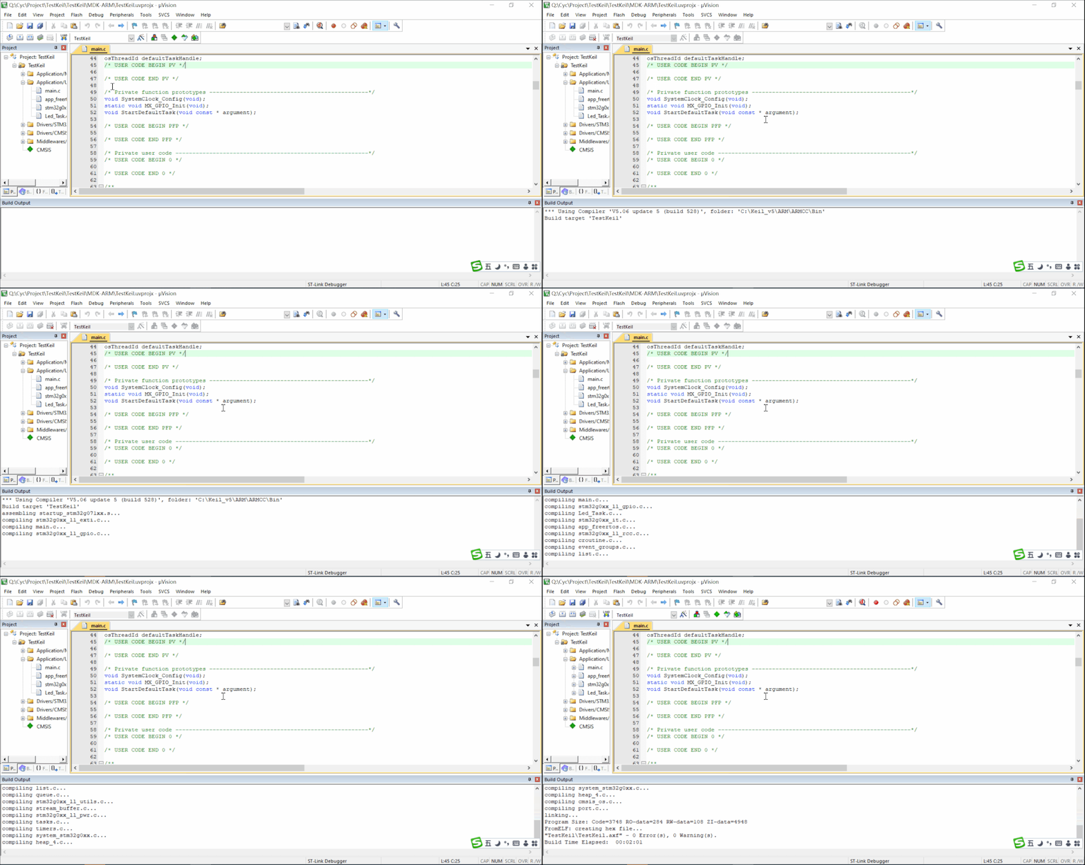
Note: If an Error message appears at this time, it will not compile successfully, and you need to modify the source code until the compile result shows 0-Error to generate the executable file properly. If a Warning message appears, you can handle it as needed; Warning messages do not affect the compilation result, but it is advisable to pay attention to these Warning messages, as many bugs are hidden within them.
7. Flashing
After the previous steps, we have obtained an executable file .axf that the machine recognizes. The project has also been configured with the corresponding programmer and chip. First, connect the programmer to the development board, then click “Project” -> “Options for Target ‘xxx'” -> “Debug” -> “Settings” to check if it is properly connected. If it is connected, you will see a flashing progress bar on the lower left.
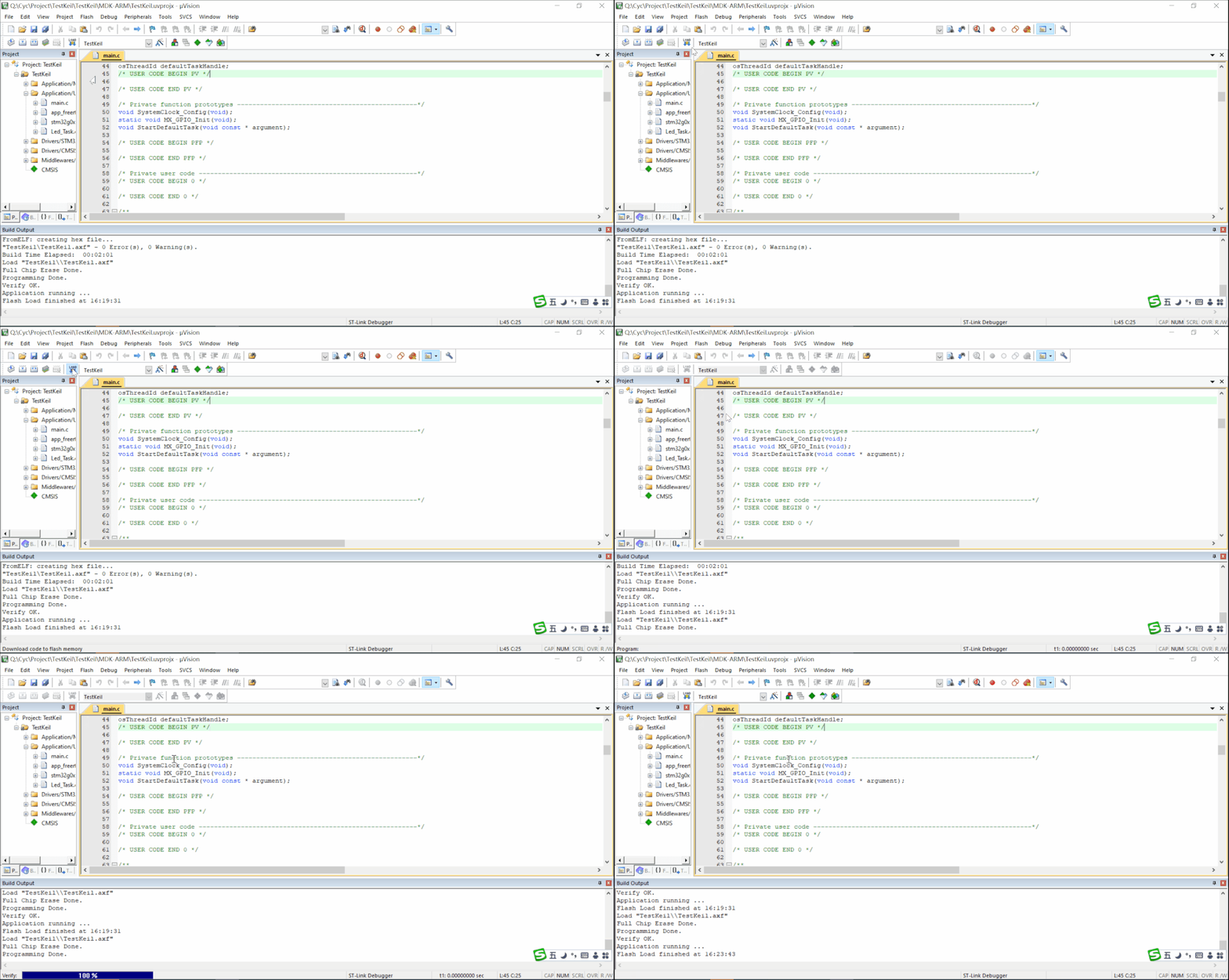
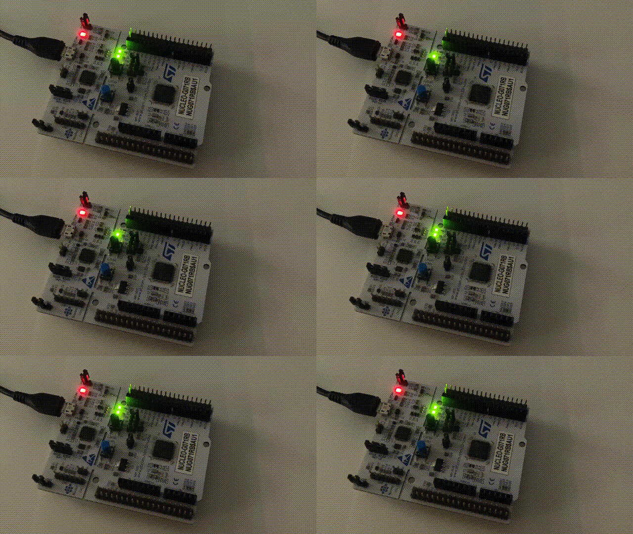
After flashing is complete, check the board; if the light starts flashing normally, it indicates that the program is running correctly.
8. Debugging
– Online Debugging
With a development board, you can flash the software into the microcontroller and use the programmer to monitor the running program in real-time. You can observe changes in the current microcontroller core, peripherals, ROM, and RAM, and Keil provides a user-friendly interface to help quickly locate and resolve issues.
– Offline Simulation
If you do not have a development board and want to roughly check if the logic you wrote has issues, you can use offline simulation. However, if the logic involves coordination with peripherals or external circuits of the microcontroller, this method is not suitable for debugging.
6. Precautions
1. The project path cannot contain Chinese characters; otherwise, it may affect compilation or debugging.
2. The project file path cannot be too long. This software has a limit on the length of path recognition; when the total path length exceeds a certain limit, compilation may report that related files cannot be found.