From Zero to One: A Comprehensive Guide to Mastering Arduino with Essential Resources for Beginners
1. Preparation: To Do a Good Job, One Must First Sharpen Their Tools
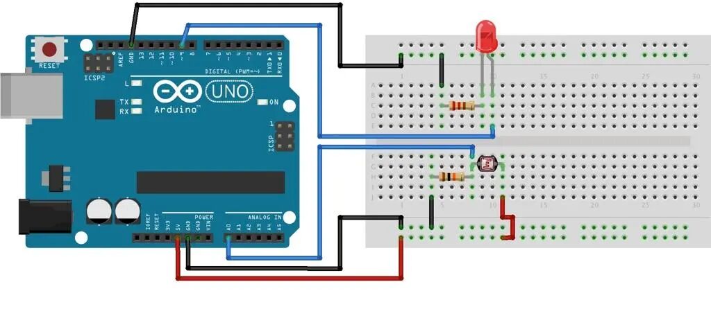
(1) Hardware Selection: Starting the Exploration Journey with “Minimal Cost”
For beginners, choosing the right hardware is crucial when stepping into the wonderful world of Arduino for the first time. First, the classic development board, such as the Arduino Uno, is highly recommended. It is considered a beginner’s artifact, offering excellent cost-performance, with countless learning resources available online, and it can easily support 99% of entry-level modules, helping you take your first step effortlessly.
Having just the development board is not enough; a basic kit is also necessary.
A breadboard allows you to freely build circuits, with various components “settling down” on it;
Dupont wires (both male-to-male and male-to-female) serve as the “bridge” connecting components, ensuring smooth signal transmission.
Additionally, an LED light is the most intuitive “little messenger” in the electronic world, indicating the circuit’s status through its on/off state. However, don’t forget to pair it with a 220Ω resistor to protect it from current surges.
Buttons are convenient for manually controlling circuit triggers; the HC-SR04 ultrasonic sensor is also indispensable. With it, you can easily measure distances and experience the wonderful interaction between the physical and digital worlds.
The total budget for these basic equipment is around 100 – 200 yuan, which meets initial exploration needs without putting too much pressure on your wallet. A reminder: some vendors offer “luxury kits” with a variety of items that may seem rich but are often unnecessary for beginners at the start. Don’t be misled; initially, focus on acquiring the core components, and as your projects progress and actual needs arise, you can add more complex modules later.
(2) Software Installation: Set Up the Development Environment in 3 Steps
Once the hardware is in place, the next step is to get the software sorted. Installing the Arduino development environment is actually quite simple; just follow these 3 steps.
-
Download the official IDE: Open your browser, visit the Arduino official website, where the interface is clear and straightforward. Find the “Software” section, click in, and you will see download options for various system versions. Whether you are using Windows, macOS, or Linux, you can find the version that fits your computer. The download process is as simple as downloading any other software, and during installation, just follow the default settings to complete it easily.
-
Configure the Chinese interface: After installing and opening the IDE, the default interface is in English, which may not be user-friendly for many. Don’t worry; you can easily switch to Chinese with a few simple steps. Click on the menu bar “File”, find “Preferences”, in the pop-up window, locate “Editor language”, click the drop-down menu, select “简体中文”, then close and reopen the IDE, and a Chinese interface of the Arduino IDE will appear before you. Now, operating it should be stress-free.
-
Driver installation: When you happily connect the development board to your computer via USB but find that the computer cannot recognize the port, you will need to install the driver. For Windows users, you can open “Device Manager”, find the unknown device with a yellow exclamation mark (usually your Arduino development board), right-click it, select “Update Driver Software”, and then manually locate the driver for installation. If you find manual installation too troublesome, you can use software like Driver Genius, which can automatically detect and install missing drivers, especially effective for drivers of domestic chips like CH340. After installing the driver, reconnect the development board, and you should see the port recognized normally in Device Manager, allowing you to happily start your Arduino programming journey.
2. Core Knowledge: Building the “Knowledge Framework” of Arduino
(1) Syntax Framework: Mastering the “Golden Duo Functions”
In the programming world of Arduino, there are two functions that can be considered the “anchor points”: setup() and loop(). Every Arduino program relies on these two core functions.
-
setup() function: Initiating the Initialization JourneyWhen you power on or reset the Arduino development board, the setup() function is the first to appear. It is like the backstage preparation work before a wonderful performance, responsible for completing various initialization settings, and this preparation work is done only once. For example, if you want to control an LED light, you first need to tell the development board that the pin connected to the LED is used for output signals, which is done using the pinMode(LED_PIN, OUTPUT) function. Here, LED_PIN is your custom pin number for connecting the LED, and OUTPUT indicates the output mode. Similarly, if you want to communicate with a computer or other devices via serial, you need to set the baud rate using Serial.begin(9600), where 9600 is the baud rate, indicating the number of data bits transmitted per second, allowing the development board and other devices to communicate at the same “rhythm”. All these initialization operations must be completed in the setup() function to lay a solid foundation for the smooth operation of subsequent programs.
-
loop() function: The “Heartbeat of the Program” that Keeps BeatingAfter the setup() function completes its mission, the loop() function shines and begins its never-ending journey of loops. It is like a tireless dancer, continuously repeating predetermined actions on the stage of the program. In this function, you can write various codes to achieve specific functionalities, such as making the LED light blink in a certain pattern. By using digitalWrite(LED_PIN, HIGH), you can turn on the LED light, then use delay(1000) to pause the program for 1000 milliseconds (1 second), and then use digitalWrite(LED_PIN, LOW) to turn off the LED light, followed by another 1-second delay. This cycle will allow you to see the LED light blinking rhythmically. This seemingly simple blinking actually contains the underlying logic of Arduino’s hardware output control, and starting from here, you can gradually understand how to make hardware work according to your ideas through code.
(2) Hardware Principles: Understanding Pins and Signal Types
To make the Arduino development board work in coordination with various external devices, you must understand its pin functions and signal types, just like mastering the various parts of a horse to ride it well.
-
Digital Pins: The “Switch Messengers” of the Digital WorldThe digital pins on the Arduino development board are marked D0 – D13, and they are mainly responsible for outputting high and low level signals, like a simple switch that can either be on (HIGH, generally corresponding to 5V or 3.3V) or off (LOW, corresponding to 0V). For example, if you want to control a small fan to turn on and off, you can connect the fan’s control pin to a digital pin on the Arduino and use the digitalWrite() function to output HIGH, causing the fan to start; outputting LOW will stop the fan. Some digital pins are also marked with a “~” symbol, indicating that they support PWM (Pulse Width Modulation) analog output. By utilizing this feature, you can adjust the brightness of an LED light by changing the duty cycle of the PWM signal, which is the proportion of high level within a cycle, allowing for fine control of the LED brightness.
-
Analog Pins: The “Data Collectors” of the Analog WorldAnalog pins are generally marked A0 – A5, and their task is to read continuously varying analog signals, such as voltage. When you connect a potentiometer to an analog pin and rotate it, its resistance value changes, causing the output voltage to vary. The Arduino’s analog pins can read this changing voltage signal. The read voltage value is converted into an integer between 0 – 1023 because the internal ADC (Analog to Digital Converter) of the Arduino maps the voltage range of 0 – 5V to a digital range of 0 – 1023. You can use the analogRead() function to obtain this digital value. For instance, the LM35 temperature sensor also works using analog pins, as its output voltage changes with temperature. By reading the value from the analog pin and performing simple calculations, you can obtain the current temperature.
-
Power and Ground: The “Energy Link” for Hardware OperationPower and ground are the basic guarantees for the normal operation of hardware. The Arduino development board typically has 5V and 3.3V power output pins. When connecting external devices, it is essential to pay attention to the voltage required by the device. For example, an OLED display generally requires 3.3V power supply; if mistakenly connected to 5V, it may burn out the display. Additionally, all external devices must share a common ground with the Arduino development board, meaning their GND pins must be connected together to ensure consistent signal reference levels, ensuring stable data transmission and device operation.
(3) Core Functions: Building the “Programming Toolbox”
The rich function library of Arduino is like a treasure chest filled with various tools. Mastering these core functions can greatly enhance your project development. Below are some commonly used functions and their application examples in the button-controlled LED project.
| Function Category | Common Functions | Example Code (Button Control LED) | Function Description |
|---|---|---|---|
| Pin Control | pinMode(pin, mode) | ||
| digitalWrite(pin, value) | |||
| digitalRead(pin) |
|
pinMode is used to set the pin as input or output; digitalWrite is used to set the high or low level of the output pin; digitalRead is used to read the state of the input pin. | |
| Analog Signal | analogRead(pin) | ||
| analogWrite(pin, value) |
|
analogRead is used to read the voltage value on the analog pin (returns 0 – 1023); analogWrite is used to output an analog signal on pins that support PWM (achieved by changing the duty cycle, value range 0 – 255). | |
| Serial Communication | Serial.begin(baud) | ||
| Serial.print(data) | |||
| Serial.read() |
|
Serial.begin is used to initialize serial communication and set the baud rate; Serial.print is used to send data to the serial port; Serial.read is used to receive data from the serial port. | |
| Timing and Interrupts | delay(ms) | ||
| millis() | |||
| attachInterrupt(interrupt, function, mode) |
|
delay pauses the program for a specified number of milliseconds; millis returns the number of milliseconds since the Arduino board was powered on; attachInterrupt is used to set up external interrupts, executing the corresponding interrupt handling function when a specified pin triggers a specific condition (such as rising edge, falling edge, level change, etc.). |
3. Practical Strategies: Driving “From Understanding to Proficiency” with Projects
(1) Phased Practical Experience: From “Lighting an LED” to “Smart Car”
The best way to learn Arduino is through hands-on practice, transforming theoretical knowledge into practical skills through interesting and useful projects. Below is a step-by-step project practice route designed to help you grow from a beginner to an Arduino expert.
Phase 1: Basic Control (1-2 Weeks)
This phase is the “toddler stage” of Arduino learning, with the main goal of familiarizing yourself with basic operations and circuit building.
- Must-Do Projects:
-
LED Blinking: This is the “Hello World” of Arduino. By controlling the LED light’s on/off state, you can understand the execution logic of the setup() and loop() functions. In the setup() function, use the pinMode() function to set the pin connected to the LED as output mode; in the loop() function, use the digitalWrite() function to output high level (on) and low level (off) to the LED pin, along with the delay() function to set the time interval for on/off, allowing you to see the LED light happily blinking.
-
Button-Controlled LED: In this project, you need to connect a button to the digital input pin of the Arduino. When the button is pressed, control the LED light’s on/off state. By using the digitalRead() function to read the button pin’s state, determine whether the button is pressed, and then use the digitalWrite() function to control the LED light based on the button state. This will help you grasp the principles of digital input and output.
-
Breathing Light: Utilize the PWM analog output function to achieve a gradual change in the LED light’s brightness, resembling human breathing. Choose a digital pin that supports PWM output (marked with a “~” symbol), and in the loop() function, continuously change the parameters of the analogWrite() function (range 0 – 255) to make the LED light’s brightness cycle from dim to bright and back, experiencing the magic of analog output.
- Core Goals:
-
Master Circuit Wiring: Learn to correctly layout electronic components on a breadboard and connect the Arduino development board to various components with Dupont wires, ensuring stable and correct circuit connections. For example, when connecting an LED light, ensure the positive terminal connects to the output pin of the development board, and the negative terminal connects to GND through a resistor; when connecting a button, one end connects to the input pin, and the other end connects to GND, with a pull-up or pull-down resistor in between to stabilize the level.
-
Code Upload Process: Become proficient in writing code in the Arduino IDE, compiling it, and uploading it to the development board. After clicking the “Upload” button, you should observe the status indicator light on the development board flashing, confirming that the code has been successfully uploaded.
-
Serial Monitor Debugging: Learn to use the Serial Monitor to view variable values and debugging information in your program. By using the Serial.print() function to output variable values in the program, open the Serial Monitor, set the baud rate (which must match the baud rate set in the program), and you can see the variable changes in real-time, making it easier to troubleshoot issues in the program.
Phase 2: Sensor Applications (2-3 Weeks)
Once you have mastered basic control, you can enter the sensor application phase, allowing Arduino to interact more with the real world.
- Classic Cases:
-
Temperature and Humidity Detection (DHT11 Sensor + OLED Display): Use the DHT11 temperature and humidity sensor to read the temperature and humidity data in the environment and display it in real-time on an OLED screen. First, you need to include the DHT library in the program (#include <DHT.h>), then define the data pin and sensor type for the DHT11 sensor. In the setup() function, initialize the sensor and OLED display; in the loop() function, use the library functions to read temperature and humidity data, and then display the data on the screen using the OLED library functions, learning the logic of library function calls and data reading and displaying.
-
Ultrasonic Distance Measurement (HC-SR04): Use the HC-SR04 ultrasonic sensor to measure distance and understand the principle of pulse signals. The HC-SR04 sensor measures distance by emitting and receiving ultrasonic waves. Its working process involves sending a short high-level pulse to the trigger pin to activate the sensor to emit ultrasonic waves, then receiving the reflected ultrasonic signal through the echo pin. In the Arduino program, use the pulseIn() function to measure the duration of the high level on the echo pin, which corresponds to the time taken for the ultrasonic wave to travel back and forth. Then, using the distance formula d = speed of sound × time / 2 (with the speed of sound generally taken as 340m/s, ensuring unit consistency by converting time to seconds), you can calculate the distance between the object and the sensor.
- Key Abilities:
-
Distinguish Between Digital/Analog Sensor Wiring Differences: Digital sensors (like DHT11, HC-SR04) output digital signals, making wiring relatively simple, generally requiring only connections for power, ground, and data pins; while analog sensors (like the LM35 temperature sensor) output analog voltage signals, requiring connections for power and ground, as well as connecting the signal output pin to the Arduino’s analog input pin.
-
Learn to Use the map() Function to Convert Signal Ranges: Often, the data range output by sensors does not match the range we need, requiring the use of the map() function for conversion. For example, if the analog sensor reads a voltage value corresponding to a digital range of 0 – 1023, and we want to convert it to a percentage range of 0 – 100, we can use the map(analogValue, 0, 1023, 0, 100) function to map analogValue from the range of 0 – 1023 to the range of 0 – 100.
Phase 3: Complex Systems (Advanced Optional)
If you have mastered the content of the previous two phases, you can challenge some more complex system projects that will test your ability to integrate knowledge and solve complex problems.
- Creative Projects:
-
Smart Obstacle-Avoiding Car: Combine the ultrasonic sensor, servos, and motor driver modules (like L298N) to create a car that can automatically avoid obstacles. The ultrasonic sensor is used to detect the distance to obstacles ahead. When an obstacle is detected, the servo controls the car’s steering, and the motor driver module controls the motor’s speed and direction, achieving the car’s obstacle avoidance function. In this project, you will need to handle multiple sensor input signals and motor output control simultaneously, testing your ability to coordinate multiple modules.
-
IoT Temperature and Humidity Monitoring: Use a Bluetooth module (like HC-05) to send data collected by the temperature and humidity sensor to a mobile app for remote monitoring. On the Arduino side, after reading the temperature and humidity data, send it out via Bluetooth serial; on the mobile side, install the corresponding app, connect to the Bluetooth device, and receive and display the temperature and humidity data, achieving IoT interaction. This process involves basic knowledge of communication protocols and mobile app development.
- Core Challenges:
-
Multi-Module Coordinated Control: In complex projects, multiple hardware modules often need to work together. How to reasonably arrange the working order of each module and manage their data interactions and logical relationships is key to project success. For example, in the smart obstacle-avoiding car project, it is essential to ensure that the ultrasonic sensor can accurately and promptly detect obstacles, and that the servo and motor can quickly respond to the sensor’s signals, requiring precise control of the timing and priority of each module.
-
Code Modularity: As project complexity increases, the amount of code will also grow. Without modular processing, the code can become chaotic and difficult to maintain and expand. Encapsulating different functional codes into independent functions or classes improves code reusability and readability. For example, encapsulate the code for reading sensor data into one function and the code for controlling motors into another function, allowing the main program to call these functions to achieve the project’s functionality. This way, the code structure is clearer, and later modifications and optimizations become more convenient.
(2) Efficient Learning Method: The “Imitate → Modify → Innovate” Three-Step Method
Learning Arduino and mastering the correct learning methods can make your efforts more effective. Here, I introduce a very practical “Imitate → Modify → Innovate” three-step learning method to help you quickly improve your Arduino skills.
-
Imitate Examples: The Arduino IDE comes with a wealth of example codes, which serve as learning “templates” that demonstrate various functional implementations. Click on the menu bar “File”, select “Examples”, and you will find a variety of example programs, such as Blink (LED blinking example), Button (button control example), etc. Run these example codes directly, observe the hardware’s response, and carefully study the code logic to understand the purpose of each line of code and how it achieves the corresponding functionality. By imitating examples, you can quickly familiarize yourself with Arduino’s basic syntax and common function usage, just like practicing calligraphy by copying characters, laying a solid foundation for future learning.
-
Modify Parameters: Based on imitating examples, try making small modifications to the code, such as adjusting delay times, changing pin numbers, or modifying sensor thresholds, and then observe the changes in the results. For instance, in the breathing light project, change the frequency of the analog output from 50ms to 20ms and see how the LED light’s brightness change speed varies; or change the pin controlling the LED light from pin 9 to pin 11 to verify if the code still works. This way, you can gain a deeper understanding of the meanings and effects of various parameters in the code and their impact on hardware behavior, while also cultivating your exploratory spirit and hands-on ability.
-
Innovate Combinations: Once you have a certain grasp of individual examples and basic functionalities, you can try integrating multiple modules’ functionalities, unleashing your creativity, and gradually forming independent project ideas. For example, control the display format of the ultrasonic distance measurement results using buttons, showing distance data in different formats on the OLED display when different buttons are pressed, or combine temperature and humidity detection with smart fan control, automatically starting the fan when the temperature exceeds a certain threshold. In this process, you will need to comprehensively apply the knowledge you have learned, thinking about how to organically combine different functional modules and solve various problems that may arise. This not only enhances your programming ability but also stimulates your innovative thinking, allowing you to truly become a creator of Arduino projects.
4. Pitfall Guide: Common Problems and Solutions for Beginners
(1) Hardware Issues: Wiring Errors and Device Failures
In the learning process of Arduino, hardware issues are the easiest to occur yet often overlooked. Below, I summarize some common hardware problems and solutions to help you quickly troubleshoot and avoid detours when encountering issues.
- Phenomenon 1: LED Not Lighting / Sensor Not RespondingThis may be one of the most common hardware problems. When you have happily built the circuit and uploaded the code, but find that the LED light is unresponsive and the sensor outputs no data, don’t panic. Follow the steps below to troubleshoot.
-
Check if the power is connected incorrectly: This is a very easy mistake to make. Reversing the positive and negative terminals may directly burn out the module, so be extra careful when connecting the circuit. Carefully check if the positive and negative terminals of the power supply match the module’s markings. For example, the 5V pin of the Arduino development board should connect to the positive terminal of the module, and the GND pin should connect to the negative terminal of the module.
-
Use a multimeter to measure pin voltage: If the power connection is correct, you can use a multimeter to measure the voltage at the pin. When the program executes digitalWrite(HIGH), the corresponding digital pin should output 5V (or 3.3V for 3.3V boards). If the measured result does not match expectations, there may be a problem. Connect the red probe of the multimeter to the pin and the black probe to GND to measure the voltage value and determine if it is normal.
-
Replace Dupont Wires: Poor contact of Dupont wires is also a common reason for hardware not responding. Sometimes, seemingly well-connected Dupont wires may have internal breaks or poor contact. Try replacing a Dupont wire and reconnecting the circuit to see if the problem is resolved. When choosing Dupont wires, try to select higher quality ones to avoid project delays due to wire issues.
- Phenomenon 2: “Port Not Found” Error When Downloading ProgramWhen you are ready to upload the written program to the Arduino development board but encounter a “port not found” error, it can be quite frustrating. However, don’t worry; the following methods can likely resolve this issue.
-
Reconnect the USB cable: Sometimes, a poor connection of the USB cable can prevent the computer from recognizing the development board’s port. First, unplug the USB cable from both the computer and the development board, then reconnect it securely and try uploading the program again. This may resolve the issue.
-
Check Tools > Port to Ensure the Correct Port is Selected: In the Arduino IDE menu bar, click “Tools” and check the “Port” option to confirm whether the correct port number is selected. Generally, when the Arduino development board is connected to the computer, a new port will appear in the “Port (COM and LPT)” section, such as COM3, COM4, etc. If the wrong port is selected, it will prompt “port not found”. If unsure which port it is, disconnect the development board, note the current port list under “Tools > Port”, then reconnect the development board and check for the new port that appears; that will be the Arduino development board’s port.
-
Replace the Data Cable: Some USB data cables only support charging and do not support data transmission. If you are using such a cable, it will prevent program uploads. Therefore, always use a USB cable that supports data transmission, preferably the one that comes with the Arduino development board. If you don’t have a suitable data cable on hand, you can purchase a reliable one from an electronics market to ensure stable data transmission.
(2) Code Issues: Compilation Errors and Logical Flaws
The code is the soul of Arduino projects; if there are issues with the code, the entire project will not function properly. Below, I introduce some common code errors and solutions to help you quickly locate and fix problems.
-
Error 1: Syntax Errors (e.g., missing semicolons, mismatched parentheses)Syntax errors are one of the most common errors in programming, and Arduino programming is no exception. For example, forgetting to add a semicolon at the end of a statement or mismatching parentheses or braces can lead to compilation errors. When a syntax error occurs, the Arduino IDE highlights the error line in red and provides an error message in the console window below. Clicking on the error message will directly locate the problematic line of code. For instance, when it says “expected ‘;’ before ‘}’ token”, it indicates that a semicolon is missing before the “}”. You just need to find the corresponding line of code and add the semicolon. To avoid such errors, it is crucial to develop the habit of “checking first (click the checkmark button on the IDE interface) before uploading”, allowing you to discover and correct syntax issues in a timely manner, ensuring the code compiles smoothly.
-
Error 2: Program Running Abnormally (e.g., sensor values jumping)Sometimes, the code can compile and upload successfully, but the program does not behave as expected, such as sensor readings fluctuating and being unstable. When encountering this situation, you can follow these steps to troubleshoot.
-
Add Serial.println() to Print Intermediate Variables: Add the Serial.println() function at appropriate places in the program to print out the values of intermediate variables, observing whether these data are reasonable through the Serial Monitor. For example, after the code that reads sensor data, add Serial.println(sensorValue) to print the value read from the sensor and check if it is within a reasonable range and if there are any abnormal fluctuations. If you find that a variable’s value is significantly abnormal, you can focus on checking the code logic related to that variable.
-
Check if the Sensor Requires a Pull-Up Resistor: Some sensors require external pull-up or pull-down resistors to stabilize levels during use. For example, button sensors can enable INPUT_PULLUP mode by default, where an internal pull-up resistor is already present, so no external resistor is needed; however, if using a regular INPUT mode, an external pull-up resistor may be necessary. If sensor values are unstable, check if it is due to the lack of a pull-up resistor, and add or adjust resistors according to the sensor’s characteristics and datasheet.
5. Advanced Directions: From “Doing Projects” to “Flexible Innovation”
(1) Make Good Use of Function Libraries: Free Your Hands and Focus on Creativity
The reason Arduino has become a favorite among makers is largely due to its rich open-source libraries. These open-source libraries are like powerful “treasure chests” that provide developers with various convenient functions, allowing you to easily meet various complex project requirements. For example, when you want to control a servo, you don’t need to write complex PWM control code; just include the servo library (like the Servo library), and you can easily control the servo angle through simple function calls. Similarly, when you need to read and write data from an SD card, the SD card library can help you quickly complete this task, greatly saving development time. Installing function libraries in the Arduino IDE is very simple. Click on the “Project” menu, select “Load Library”, then click “Manage Libraries”. In the pop-up library manager window, you can see various libraries. Enter the name of the library you want to install in the search box, such as “Servo” or “SD”, to quickly find the corresponding library, then click the “Install” button and wait for the installation to complete. After installation, use the #include statement in your code to include the library file, and you can start using the various functions in the library. For example, when using the DHT11 temperature and humidity sensor to read data, you only need three simple lines of code:
#include <DHT.h>\n#define DHTPIN 2\n#define DHTTYPE DHT11\nDHT dht(DHTPIN, DHTTYPE);\nvoid setup() {\n Serial.begin(9600);\n dht.begin();\n}\nvoid loop() {\n float humidity = dht.readHumidity();\n float temperature = dht.readTemperature();\n Serial.print("Humidity: ");\n Serial.print(humidity);\n Serial.print(" %\t");\n Serial.print("Temperature: ");\n Serial.print(temperature);\n Serial.println(" °C");\n delay(2000);\n}In this code, the DHT library is first included, and then the data pin and type of the sensor are defined. In the setup() function, serial communication and the sensor are initialized; in the loop() function, the dht.readHumidity() and dht.readTemperature() functions are used to read humidity and temperature data, which are printed out via the Serial Monitor. This is the charm of function libraries, making complex functionalities simple and understandable, allowing you to focus more on the creativity and overall architecture of your projects.
(2) Expand Applications: Connecting the “Real World” with the “Digital World”
Once you have a certain grasp of Arduino’s basic operations and project development, you can try to expand its application areas, connecting the “real world” with the “digital world” to achieve more interesting and practical functionalities.
-
Internet of Things (IoT): Remote Monitoring at Your FingertipsThe Internet of Things is a hot field in today’s technological development, and Arduino performs excellently in IoT applications. By using WiFi modules like ESP8266/ESP32, Arduino can easily connect to the internet, uploading data collected by sensors to the cloud for remote monitoring and control. For example, in temperature and humidity monitoring, you can use the DHT11 temperature and humidity sensor to collect environmental data, then send it to the Blynk platform via the ESP8266 module. By installing the Blynk app on your phone, you can view temperature and humidity data anytime and anywhere, and set thresholds to receive alerts when temperature and humidity exceed the set range. In terms of code implementation, you first need to include the ESP8266WiFi library and the Blynk library, then initialize the WiFi connection and Blynk client in the setup() function, and in the loop() function, read temperature and humidity data and send it to the Blynk platform.
-
Hardware Interaction: Creative Enclosures for Unique WorksIn addition to software-level expansions, there is also much to explore in hardware interaction. By combining 3D printing and laser cutting technologies, you can create unique enclosures and panels for Arduino projects, enhancing the aesthetics and practicality of your works. For example, if you create a smart car, you can use 3D printing technology to print a cool car body shell, which not only protects the internal electronic components but also makes the car look more unique; or use laser cutting to create an acrylic panel for your temperature and humidity monitoring device, engraving exquisite patterns and labels on it to give the entire device a more technological feel. In this process, you will need to learn some basic 3D modeling and laser cutting software usage to turn your ideas into actual works.
(3) Community Resources: Learning by Standing on the “Shoulders of Giants”
Arduino has a large and active community, gathering the wisdom and experience of countless developers. Fully utilizing community resources is like standing on the shoulders of giants, allowing you to avoid many detours and quickly improve your skills.
-
Official Documentation: Authoritative Guide for Anytime ReferenceThe “Reference” section of the Arduino official website is one of the most authoritative learning materials, detailing the usage of each function, including function parameters, return values, and rich example codes. When you encounter problems during programming and are unsure how to use a certain function, consulting the official documentation often provides the most accurate answers. For instance, when you want to understand the specific usage of the analogWrite() function, you can find its syntax format, applicable pin ranges, and how to achieve PWM output through this function, along with practical example codes for reference.
-
Forums and Communities: Exchange and Progress TogetherStack Exchange is a well-known technical Q&A community where many questions and answers about Arduino can be found. You can search for the problems you encounter here or ask other developers for professional advice and help. The Arduino Chinese community is a gathering place for Arduino enthusiasts in China, where you can exchange experiences with local developers, share your project achievements, and learn about the latest Arduino dynamics and resources in the country. Additionally, there are many Arduino tutorial videos on platforms like Bilibili and Douyin. By searching for “Arduino tutorials”, you can find a wealth of practical videos made by enthusiasts, allowing you to learn Arduino knowledge and skills more intuitively.
-
Open Source Platforms: Borrowing Code to Inspire CreativityGitHub is the world’s largest open-source code hosting platform. By searching for “Arduino projects” on it, you can find a vast amount of open-source project code. These codes cover various fields and application scenarios. For example, searching for “Arduino smart home” will yield many smart home-related project codes. You can refer to the architecture, functional implementation methods, and coding styles of these codes for inspiration, stimulating your creativity. At the same time, you can also share your project code on GitHub, interacting with developers worldwide and contributing to the open-source community.
Conclusion: From “Maker Novice” to “Creative Expert”, Just One Step Away!
The charm of Arduino lies in its ability to “realize creativity without barriers”—whether it’s making an LED blink to music or creating a self-watering flower pot, every small project is a process of “turning ideas into reality”. Remember: when encountering problems, transform “why the error occurred” into “how to troubleshoot and solve it”, and you will find yourself breaking through bottlenecks unconsciously. Now, pick up your development board and start your maker journey by lighting up your first LED light!