Click on the blue text
Follow us

Working Principle
When a node (station) on the CAN bus sends data, it broadcasts it in the form of a message to all nodes on the network. For each node, regardless of whether the data is intended for itself, it still receives it.
The first 11 bits of each message serve as an identifier, defining the priority of the message. This message format is known as a content-oriented scheme. In the same system, the identifier is unique, meaning that two stations cannot send messages with the same identifier. This configuration is crucial when several stations compete to read from the bus.
We understand the general working principle, but we still need to put in some effort to grasp the fundamental protocol. Here, we introduce an important term: “dominant” and “recessive”:
First, the CAN data bus consists of two wires: one is yellow, and the other is green. These are the CAN_High and CAN_Low lines. When in a resting state, the voltage levels on these two wires are the same, known as the static level, approximately 2.5 volts.
This static level state is referred to as the recessive state, also known as the recessive level, which is the state when there is no interference. When a signal changes, the voltage on the CAN_High line increases, generally by at least 1V; meanwhile, the voltage on the CAN_Low line decreases by the same amount, also 1V.
At this point, CAN_High is at 2.5V + 1V = 3.5V, thus it is in the active state. Meanwhile, CAN_Low drops to 2.5V – 1V = 1.5V. You can see this in the following diagram:
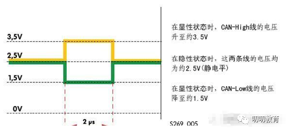
This shows that in the recessive state, there is no voltage difference between the CAN_High and CAN_Low lines, meaning we see no changes and cannot detect a signal. However, in the dominant state, the minimum value is 2V, allowing us to utilize this change to transmit data. This leads to the formation of frames, fields within those frames, and bits within those fields.
On the bus, a logical 1 typically represents recessive, while 0 represents dominant. These 1s and 0s can be utilized to transmit data. By leveraging this voltage difference, we can receive signals.
Generally, the control unit is connected to the CAN driver bus through a transceiver, which (as the name implies) can send and receive. Inside this transceiver is a receiver, which is a differential signal amplifier located on the receiving side. This amplifier naturally amplifies the voltage difference between the CAN_High and CAN_Low lines and transmits it to the receiving area, as shown in the diagram below:
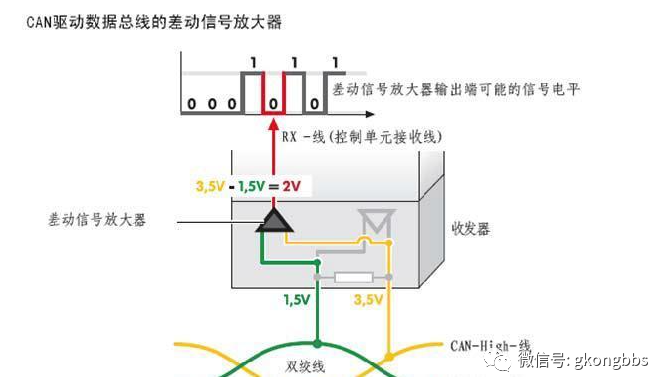
From the above diagram, we can see that when there is a voltage difference, the differential signal amplifier amplifies the transmission, converting the corresponding data bits into 0.
Key Difficulty: Messages
A message refers to the data packet to be transmitted over the CAN bus. For safety, we need to encode the data packet we are transmitting with a protocol to minimize errors, which leads to the creation of numerous frames, arbitration, and CRC checks. These are all challenging aspects.
The concept of an identifier is, as the name suggests, to distinguish different messages by identifiable character bits. There are standard and extended identifiers. The standard is 11 bits, while the extended is 29 bits. Its function is to provide priority, determining which message is transmitted first—the smaller the identifier value, the higher the priority of the message.
CAN message formats come in two types; the difference lies in the length of the identifier. A frame with an 11-bit identifier is called a standard frame, while a frame with a 29-bit identifier is called an extended frame. CAN messages have the following four different frame types:
(1) Data Frame: The data frame transmits data from the sender to the receiver;
(2) Remote Frame: A bus node issues a remote frame, requesting the transmission of a data frame with the same identifier;
(3) Error Frame: Any node that detects a bus error sends an error frame;
(4) Overload Frame: The overload frame is used to provide additional delay between preceding data frames (or remote frames).
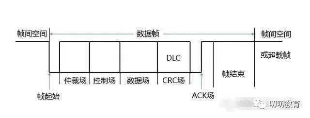
First, let’s study the data frame. The data frame consists of seven different bit fields (frame start, arbitration field, control field, data field, CRC field, acknowledgment field, frame end).
The bit fields are combinations of different bits; the naming can be quite abstract. Let’s take a look at these different bit fields. Initially, there is a frame start bit, also called SOF. It is represented by a dominant bit, which is 0; it indicates that there is a voltage difference on both lines, meaning data is present.
This frame start bit may seem simple, but it is not trivial. To ensure that all sub-stations synchronize with the sending station of the message, many factors must be considered.
The next field is the arbitration field. This arbitration is quite abstract; it is essentially designed to solve a problem. If two or more units start transmitting messages simultaneously, a bus access conflict occurs, and the arbitration mechanism is used to eliminate lower-priority data one by one based on identifier priority. We can vividly describe this battle for bus access.
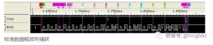
When the bus is in a recessive state, it is at a recessive level, and at this time, any node can send a dominant level as the start of the frame. If two or more nodes simultaneously send, they start competing for the bus, but only one can seize it. How do we determine who stays and who goes? We begin to consider the identifier we previously defined; the identifier has priority, and the smaller it is, the higher the priority. So how is this accomplished? See the diagram below:
First, let’s clarify two points:
1. In the diagram below, the low waveform represents 0 (dominant), while the high waveform represents 1 (recessive); 2. When recessive meets dominant, it becomes dominant.
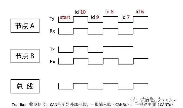
As shown in the diagram, nodes A and B have the same levels for the 10th, 9th, and 8th bits of their identifiers, so both nodes receive the same information they sent. At the 7th bit, node B sends a “1”, but the message received from the node is “0”.
Why? Because node A simultaneously sends a dominant bit, making the bus become dominant, which is 0. Node B will exit sending and switch to pure listening mode without sending data; node A successfully sends the arbitration bit and gains control of the bus, subsequently sending the entire message.
The signal on the bus continuously tracks the last node that gained control of the bus and transmitted the message; in this example, the message from node A will be tracked. The advantage of this non-destructive bit arbitration method is that before the network determines which node is transmitting, the starting part of the message has already been transmitted over the network, allowing high-priority node data transmission without any delay.
During the data transmission process of the node that gains control of the bus, other nodes become the receiving nodes of the message and will not send messages again until the bus is free. In this bit-by-bit comparison, ultimately, node B loses the bus due to the deviation in the 7th bit. From then on, it simply listens, and the control passes to node A. This is the arbitration mechanism.
As mentioned earlier, there are two formats for messages: standard and extended. Here, the arbitration fields differ between the two formats. In the standard format, the arbitration field consists of an 11-bit identifier and an RTR bit.
However, in the extended format, it includes a 29-bit identifier, SRR bit, IDE bit, and RTR bit.
The RTR bit, Remote Transmission Request BIT, must be a dominant 0 in data frames but is recessive 1 in remote frames.
The SRR bit, which replaces the remote request bit, is a recessive bit, meaning it is 1, and it occupies the position of the RTR bit in the extended format standard frame. This is why the standard frame has priority over the extended frame; after transmitting the 11-bit identifier (the last 18 bits of the extended frame are sent last), the RTR bit of the standard frame and the SRR bit of the extended frame are sent.
At this point, the RTR of the standard frame is dominant, while the SRR of the extended frame is recessive, allowing the bus to be occupied by the standard frame.
Simultaneously, the earlier question becomes clear; the designers of the CAN bus protocol definitely designed data frames to have priority over remote frames. Therefore, the IDE (Identifier Extension Bit) belongs to the arbitration field of the extended format.
For the extended format, the IDE bit belongs to the arbitration field; for the standard format, the IDE bit belongs to the control field. The IDE bit in the standard format is “dominant”, while the IDE bit in the extended format is “recessive”.
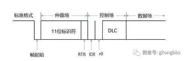
▲ Data Frame in Standard Format
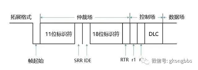
▲ Data Frame in Extended Format
The control field consists of 6 bits, and the formats of the control fields differ between the standard and extended formats. The frame in the standard format includes a data length code, IDE bit (which is a dominant bit), and a reserved bit r0. The frame in the extended format includes a data length code and two reserved bits: r1 and r0. These reserved bits must be sent as dominant, but the receiver accepts any combination of “dominant” and “recessive” bits. The structure is illustrated in the diagram below:
▲ Control Field Structure
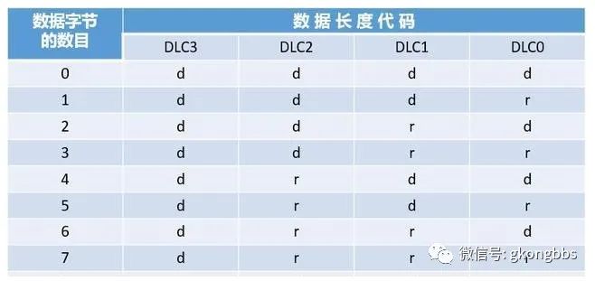
The Data Length Code (DLC) for both standard and extended formats is shown in the table below:

▲ Data Frame Length Code DLC
The data length code indicates the number of bytes in the data field. Here, d represents “dominant”, and r represents “recessive”; the allowed number of data bytes in a data frame is {0, 1, …, 7, 8}. Other values are not permitted.
The data field consists of the data sent in the data frame. It can be 0 to 8 bytes, with each byte containing 8 bits, starting with the most significant bit (MSB).
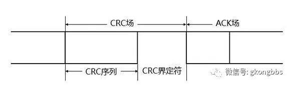
The cyclic redundancy check (CRC) field is one of the most commonly used error-checking codes in data communication, characterized by the ability to select arbitrary lengths for both the information field and the check field.
The CRC field includes the CRC sequence (CRC Sequence), followed by the CRC delimiter (CRC Delimiter), structured as shown in the diagram:
The basic principle for generating a CRC code: Any code composed of a binary string can correspond one-to-one with a polynomial that only takes values of ‘0’ and ‘1’. For example, the code 1010111 corresponds to the polynomial x6+x4+x2+x+1, while the polynomial x5+x3+x2+x+1 corresponds to the code 101111.
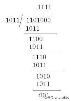
Refer to the example below and reflect on it yourself! Given the information bits 1101 and the generating polynomial G(x)= x3+x+1, find the CRC code.
The information sequence to be transmitted is 1101, with 3 zeros added at the end corresponding to the highest degree of the given polynomial x^3, resulting in: 1101000;
Using the polynomial G(X)=X3+X+1, the binary encoding for degree 1 is: 1011; 1101000 is divided by 1011 using modulo 2, and the remainder obtained is the check code. Adding the check code to the original data results in the desired encoding, thus the actual data sequence sent is 1101001. The process of calculating the check code is illustrated in the diagram below:
Acknowledgment Field (ACK Field) The acknowledgment field has a length of 2 bits, including the acknowledgment slot (ACK Slot) and the acknowledgment delimiter (ACK Delimiter), as illustrated in the diagram. In the ACK field, the sending node sends two “recessive” bits.
When the receiver correctly receives a valid message, it sends a “dominant” bit to the sender during the acknowledgment slot to acknowledge receipt.
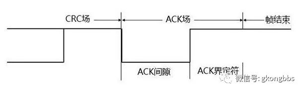
Frame End Each data frame and remote frame is defined by a flag sequence. This flag sequence consists of 7 “recessive” bits.
2. Remote Frame By sending a remote frame, the bus node issues a request to the previously sent data frame node to send it again. Which data frame to send is determined by the identifier of the remote frame.
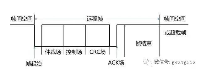
Similar to the data frame, the remote frame also has standard and extended formats and consists of 6 different bit fields: frame start, arbitration field, control field, CRC field, acknowledgment field, and frame end.
In contrast to the data frame, the RTR bit of the remote frame is “recessive”. It does not have a data field, and the value of the data length code (DLC) is unrestricted (it can be any value within the allowed range of 0-8), corresponding to the data length code of the data frame. The structure of the remote frame is illustrated in the diagram below:
3. Error Frame The error frame consists of two different fields: the first field is the overlay of the error flags provided by different nodes (Error Flag), and the second field is the error delimiter.
To correctly terminate the error frame, the node that “acknowledges the error” requires the bus to be idle for at least 3 bit times. Therefore, the bus load should not be 100%. The structure of the error frame is illustrated in the diagram:
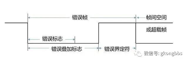
(In the diagram, for uniformity, the error frame is corrected to the error frame)
(1) Error Flag There are two forms of error flags: the active error flag and the acknowledgment error flag. The active error flag consists of 6 consecutive “dominant” bits; the acknowledgment error flag consists of 6 consecutive “recessive” bits, unless overwritten by other nodes’ “dominant” bits.
(2) Error Delimiter The error delimiter consists of 8 “recessive” bits.
After the error flag is transmitted, each node sends a “recessive” bit and continuously monitors the bus until it detects a “recessive” bit, then begins to send the remaining 7 “recessive” bits.
4. Overload Frame The overload frame consists of two bit fields: the overload flag and the overload delimiter, structured as shown in the diagram:
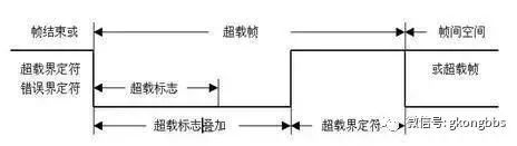
▲ Overload Frame Structure Diagram
Three overload conditions can trigger the transmission of the overload flag: the internal condition of the receiver requires delaying the next data frame and remote frame.
During the first and second bytes of intermission, a “dominant” bit is detected. Here, we have a concept of intermission. We can talk about it. Intermission is part of the frame interspace. It consists of three recessive bits. During the intermission, all stations are not allowed to transmit data frames or remote frames. The only thing it can do is indicate an overload condition.
If a CAN node samples a dominant bit at the 8th bit (the last bit) of the error delimiter or overload delimiter, the node will send an overload frame. This frame is not an error frame, and the error counter will not increase.
(1) Overload Flag The overload flag consists of 6 “dominant” bits. All forms of the overload flag are the same as the active error flag.
(2) Overload Delimiter The overload delimiter consists of 8 “recessive” bits.
5. Frame Interspace The isolation between data frames (or remote frames) and preceding frames is achieved through the frame interspace, regardless of the type of preceding frame (data frame, remote frame, error frame, overload frame).
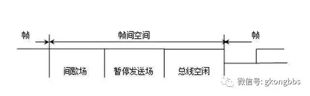
The frame interspace includes intermission and idle bits of the bus. If a node that “acknowledges the error” has been the sender of the previous message, its frame interspace includes, in addition to intermission and idle bits, a field called “suspend transmission” (Suspend Transmission).
For nodes that are not “acknowledging the error” or those that are receivers of the previous message, the frame interspace is shown in the diagram:
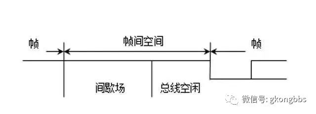
▲ Non-“Acknowledging Error” Frame Interspace
For the node that was the sender of the previous message and is “acknowledging the error”, its frame interspace is shown in the diagram:
(1) Bus Idle The idle time of the bus is arbitrary. As long as the bus is deemed idle, any node waiting to send a message will access the bus. During the transmission of other messages, if a message is suspended, its transmission will begin with the first bit after the intermission. The “dominant” bits detected on the bus can be interpreted as the start of a frame.
(2) Suspend Transmission After a node that “acknowledges the error” sends a message, it sends 8 “recessive” bits following the intermission before the next message begins transmission or before the bus is idle. If another node starts sending a message simultaneously (triggered by another node), this node will act as the receiver for this message.
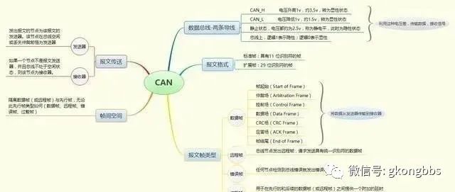
Finally, let’s summarize with a mind map:
Here are a few photos of the actual product:

Source: Internet, infringement will be deleted