Communication is carried out through the following 5 types of frames.
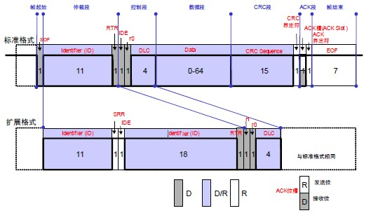
Additionally, the Data Frame and Remote Frame have both standard and extended formats. The standard format has an 11 bit identifier (Identifier: hereafter referred to asID), while the extended format has a 29 bitID.
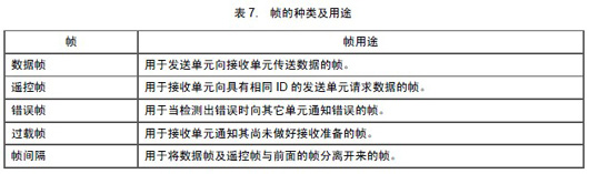
The purposes of various frames are shown in Table 7 and the composition of various frames is illustrated in Figures 1 to 5 below.
Figure 1.Composition of Data Frame
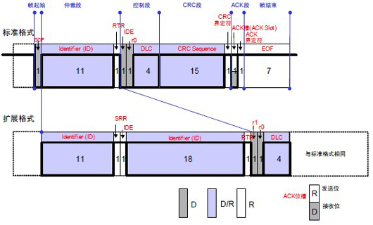
Figure 2. Composition of Remote Frame
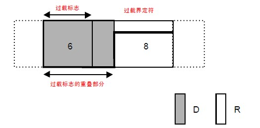
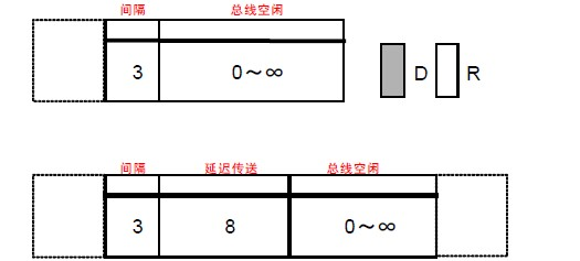
Figure 5. Frame Separation
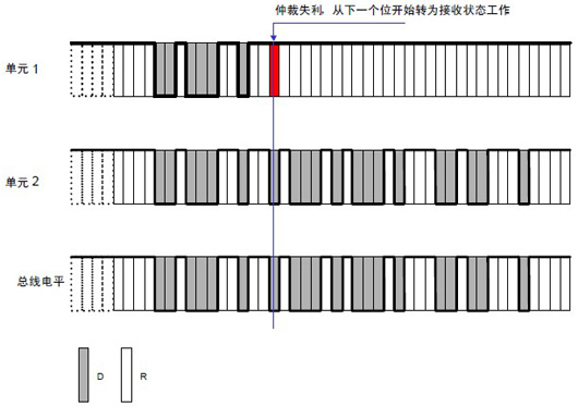
In the idle state of the bus, the unit that starts sending messages first gains the right to send.
When multiple units start sending simultaneously, each sending unit performs arbitration starting from the first bit of the arbitration segment. The unit that outputs the dominant level the longest can continue to send.
The arbitration process is illustrated in the figure below.
Figure.Arbitration Process
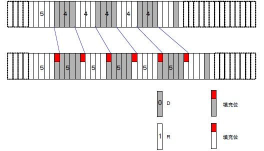
Bit stuffing is a function set to prevent burst errors. When the same level persists for 5 bits, a bit of inverted data is added.
Bit stuffing composition is illustrated in the figure below.
(1) Operation of Sending Unit When sending Data Frames and Remote Frames,SOF~CRC between data, if the same level persists for5 bits, a 1 bit with inverted level is inserted at the next bit (the6 th bit).
(2) Operation of Receiving Unit When receiving Data Frames and Remote Frames,SOF~CRC between data, if the same level persists for5 bits, the next bit (the6 th bit) needs to be deleted before receiving. If this 6th bit’s level is the same as the previous 5 bits, it will be considered an error and an error frame will be sent.
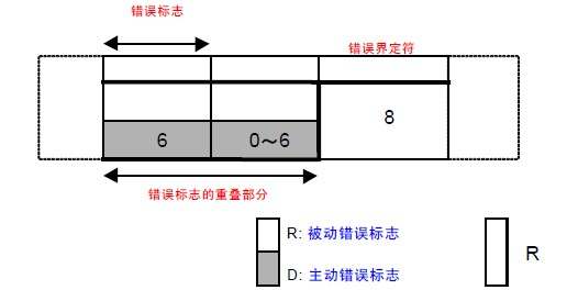
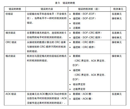
There are5 types of errors. Multiple errors may occur simultaneously.
The types of errors, error contents, error detection frames, and detection units are shown in Table 9 .
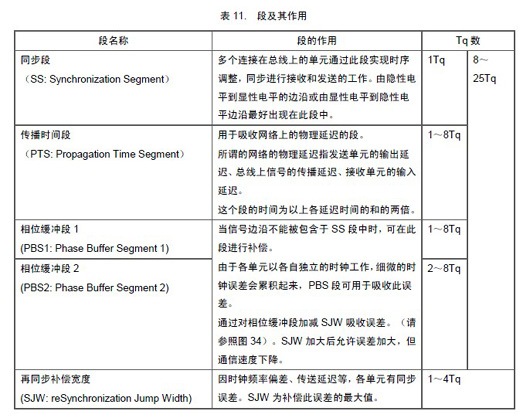
The number of bits sent per second by the sending unit in an asynchronous state is called the bit rate. One bit can be divided into 4 segments.
● Synchronization Segment(SS)
● Propagation Time Segment(PTS)
● Phase Buffer Segment 1(PBS1)
● Phase Buffer Segment 2(PBS2)
These segments are composed of the smallest time unit called Time Quantum (hereafter referred to asTq).
1 bit is divided into4 segments, each segment is composed of severalTq units, which is referred to as bit timing.
1 bit consists of how manyTq units, how manyTq units each segment consists of, etc., can be arbitrarily set for bit timing. By setting the bit timing, multiple units can sample simultaneously, and sampling points can be set arbitrarily.
The functions of each segment and the number of Tq units are shown in Table11 . The composition of 1 bit is illustrated in the figure below.
6. Methods for Achieving Synchronization
CAN protocol communication method is NRZ (Non-Return to Zero). There are no additional synchronization signals at the beginning or end of each bit. The sending unit begins sending data in synchronization with the bit timing. Additionally, the receiving unit synchronizes and receives based on the changes in the bus level. However, clock frequency errors in the sending and receiving units and phase delays in the transmission path (cables, drivers, etc.) can cause synchronization deviations. Therefore, the receiving unit adjusts its timing through hardware synchronization or resynchronization methods during reception.
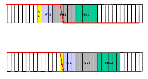
6.1 Hardware Synchronization
The receiving unit performs synchronization adjustments when detecting the frame start during the bus idle state.
When detecting the edge, the value of SJW is not considered, and it is assumed to be the SS segment. The hardware synchronization process is illustrated in the figure below.
Hardware synchronization process is illustrated in the figure below.
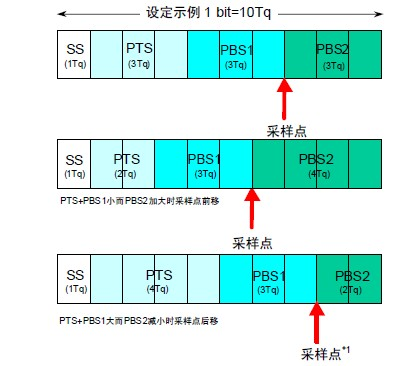
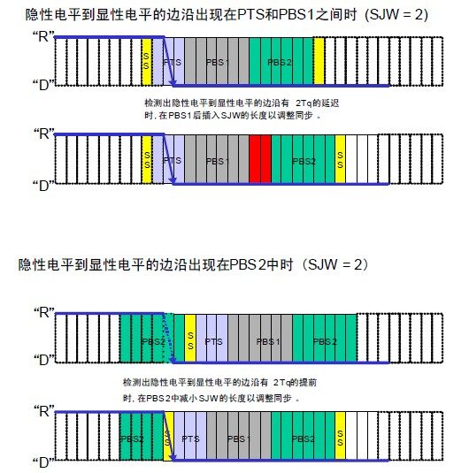
Synchronization adjustments made when detecting changes in bus levels during reception.
Whenever an edge is detected, synchronization is adjusted by lengthening the PBS1 segment or shortening the PBS2 segment based on the SJW value. However, if an error exceeding the SJW value occurs, the maximum adjustment cannot exceed the SJW value.
Resynchronization is illustrated in the figure below.
6.3 Rules for Adjusting Synchronization
Hardware synchronization and resynchronization follow the following rules:
(1) Only one synchronization adjustment is made within 1 bit.
(2) Only if the bus value at the last sampling point is different from the bus value after the edge, can that edge be used for synchronization adjustment.
(3) When the bus is idle and there is an edge from a dominant level to a recessive level, hardware synchronization must be performed.
(4) If an edge from a dominant level to a recessive level detected when the bus is not idle satisfies conditions (1) and (2), resynchronization will be performed. However, it must also satisfy the conditions below.
(5) If the sending unit observes a delay in its own output of the dominant level, it will not perform resynchronization.
(6) If multiple units are sending simultaneously from the start of the frame to the arbitration segment, the sending unit will not perform resynchronization on the delayed edge.
(Images sourced from the internet)
Click the mini-program below to view more repair cases