Skip to content
【2024 First Release】The Drone Giveaway Activity Returns! More Writing, More Rewards!
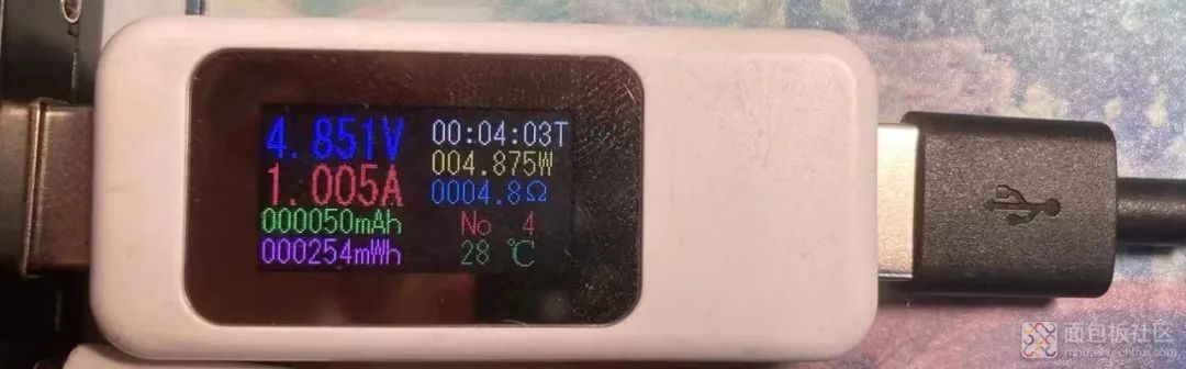
The USB power meter is an essential tool for engineers! It’s commonly used to measure the current of phones, products, and circuits. I previously purchased a small power meter, which is very convenient for measuring the power of power banks and lamps. This power meter also has the function of calculating discharge capacity and recording time, allowing me to measure the capacity of power banks and discharge times.
Now I can disassemble this power meter to examine the material costs inside and analyze the current and voltage sampling circuits.
Since this disassembly analysis is very detailed, the later sections will include circuit diagrams and analyses of the sampling circuits for reference. If you have any questions, we can learn and discuss together!
Appearance Display & Nameplate Explanation
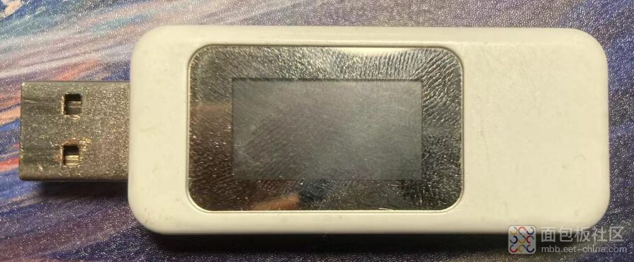
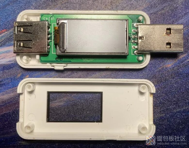
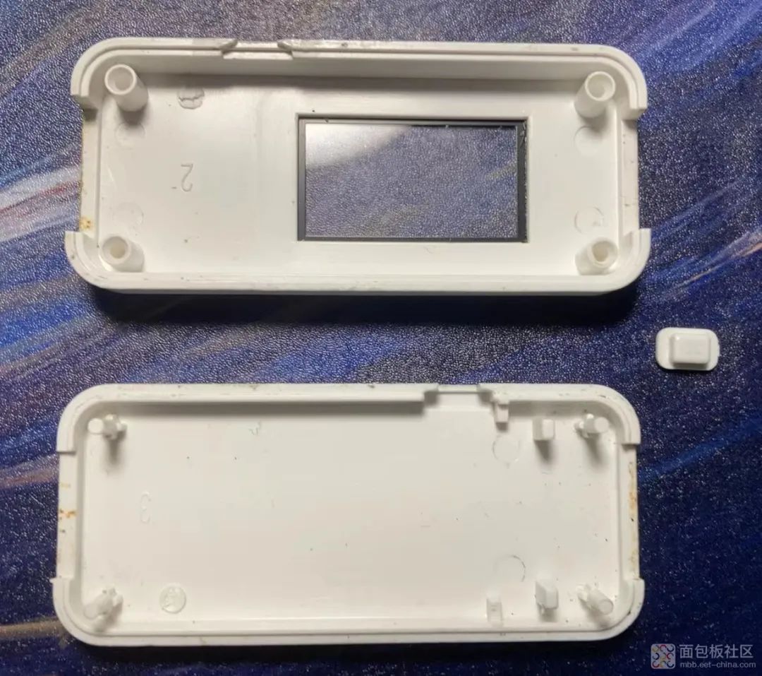
(1) The shell is made of hard plastic, with a button hole on the side, and USB ports on the front and back. The front features a screen, approximately 1 inch in size, with a black border around it, making the actual screen size smaller than it appears.
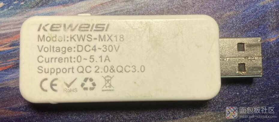
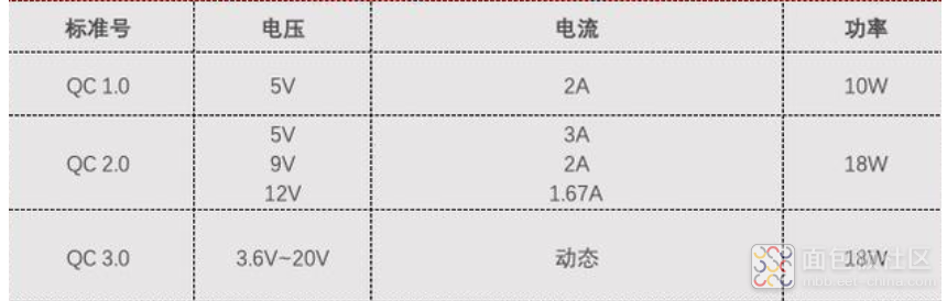
(2) The brand name and model can be ignored. It shows that the Voltage is: DC 4–30V, Current 0–5.1A, and it supports QC2.0 & QC3.0 protocols.
The CE mark is a safety mark for the European common market, indicating that the product complies with relevant EU directives.
The RoHS mark indicates that certain harmful substances are restricted in electrical and electronic equipment, meaning this power meter is harmless.
Green environmental protection mark
The trash can with an X means that when you plan to dispose of this product, it must be sent to appropriate facilities for recycling and reuse.
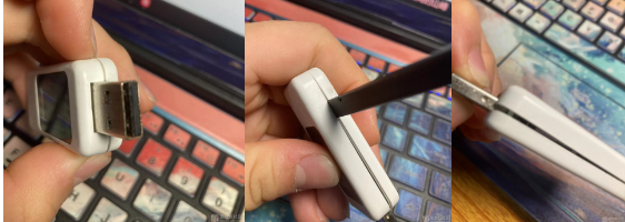
(4) The shell is made of two pieces, which can be pried open, but there are pillars around it that must be avoided when disassembling to prevent breaking them.
(1) First, since the shell is made of upper and lower parts, you can insert your fingernail or a pointed object into the gap of the shell and gently pry it open. Then insert a pry tool along the edge and slowly slide it while prying until the four corners of the shell are lifted, allowing you to separate the shell. The sides of the shell are not glued, which is great! This may also be to save costs or make rework easier!
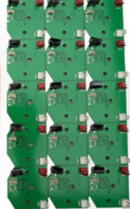
(2) After opening, I found that the PCB board is not fixed with screws but is directly mounted on the support pillars, which may also be to save costs, but this method of fixing is quite sturdy!
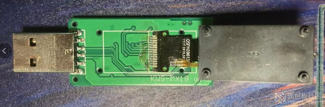
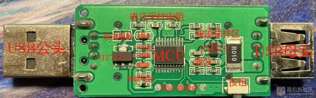
(1) Looking at the PCB board, the MCU is polished! Actually, polishing is not entirely a bad thing because a polished MCU can still be identified, as only commonly used chips need to be polished; custom chips may not even have silkscreen (you can see how I found this chip later!).
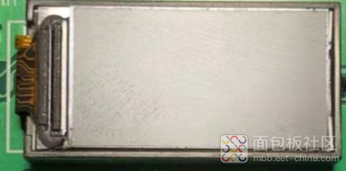
(2) The screen is also fixed to the PCB board through four holes, which is well done.
(3) There are many vias on the back of the screen, while there are almost none on the front, so the surface components can likely be measured for continuity with a multimeter.
(4) The screen has 13 pins, and based on the displayed color and the number of pins, it is determined to be primarily a TFT screen, so the subsequent analysis mainly focuses on TFT screens.
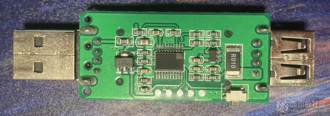
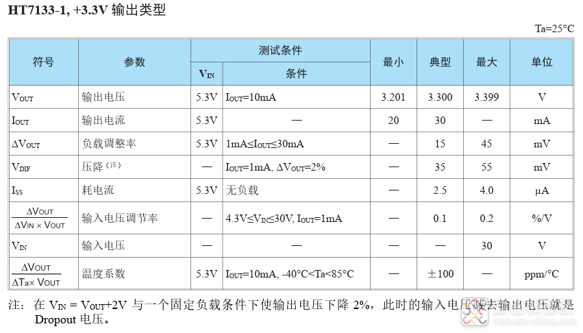
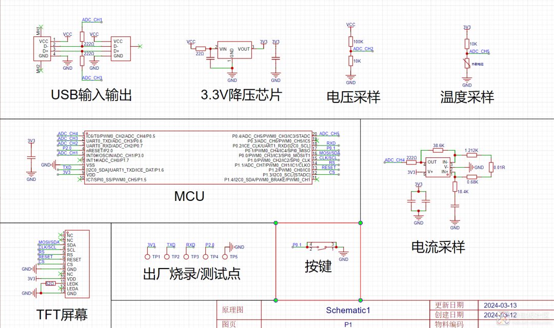
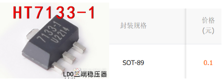
HT7133-1, since the MCU/screen and other components require 3.3V, this chip’s main function is to step down, allowing an input voltage of 30V and an output voltage of 3.3V.
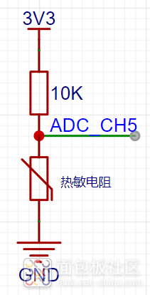
NTC Temperature Measurement (Thermistor) The resistance of the thermistor decreases as the temperature rises. The MCU’s ADC detects changes in the circuit voltage, inferring the current temperature.
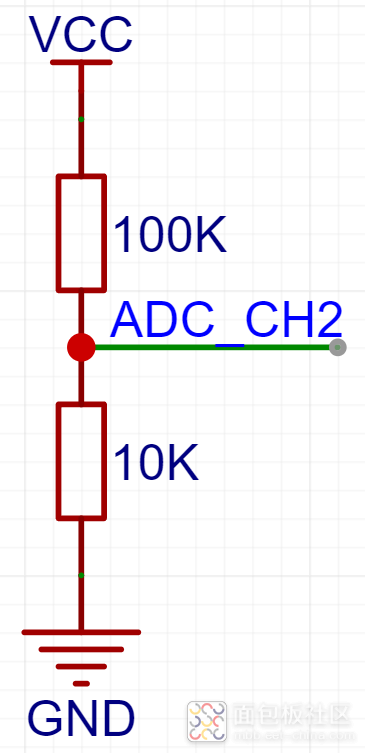
Voltage Sampling Area Through resistors, the input voltage can be divided to a level detectable by the MCU’s ADC, approximately 0-3.3V, allowing the ADC to directly sample the input voltage.
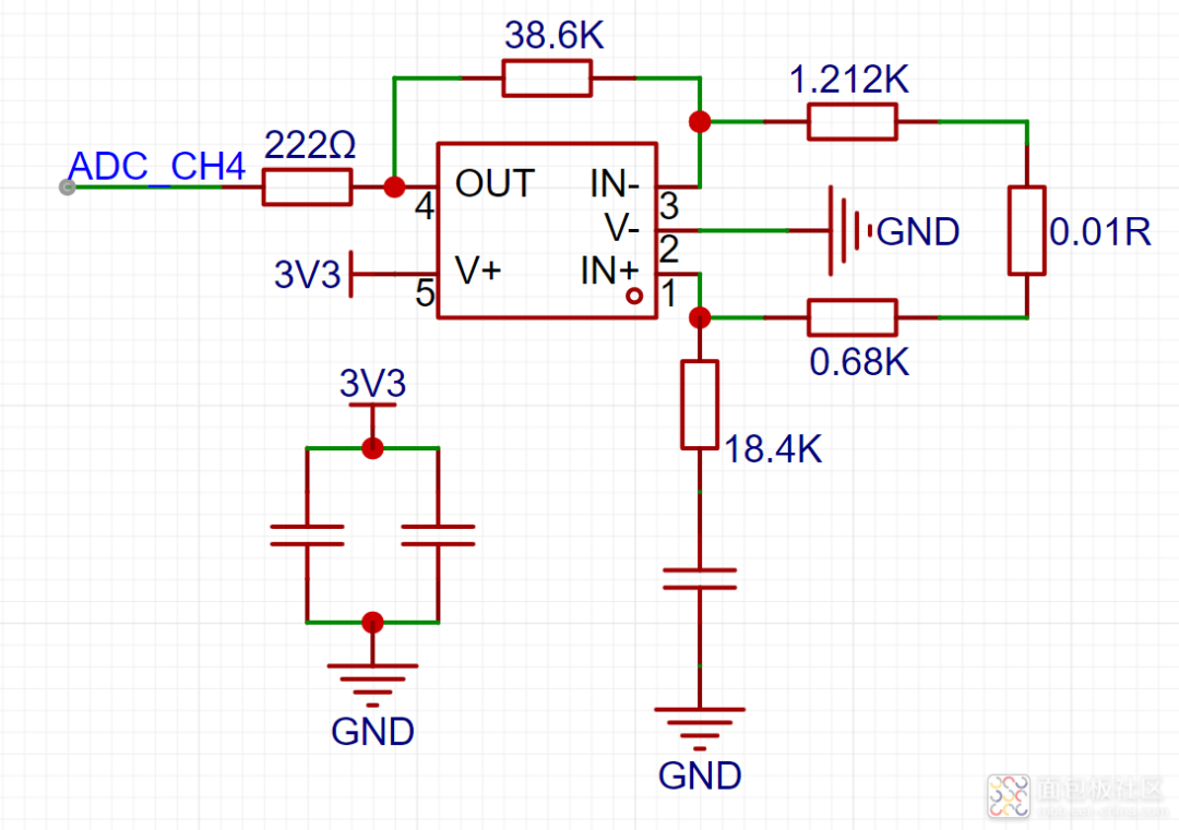
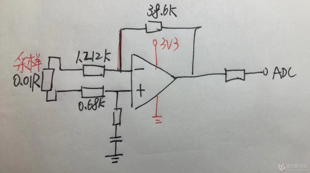
Current Sampling Area Through an operational amplifier, since the value of the sampling resistor is very small, it causes a small voltage drop, so the operational amplifier needs to amplify it before sampling. The value of the sampling resistor is 0.01R.
[The resistors in the following figures are approximate measurements! They may not be accurate!]
Operational Amplifier Circuit Analysis
1. The operational amplifier samples a differential amplification circuit, which can effectively suppress common-mode noise compared to a single-ended amplification circuit, providing a larger dynamic range and signal-to-noise ratio.
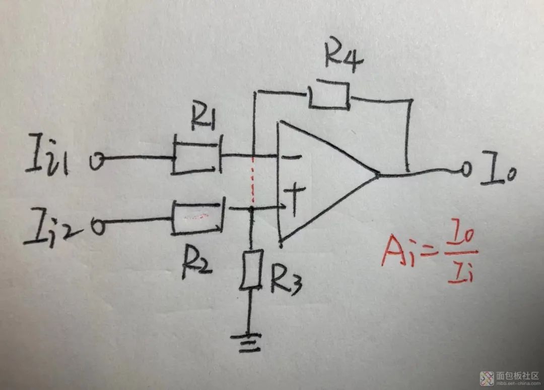
2. The amplification gain calculation is shown in the following figure.
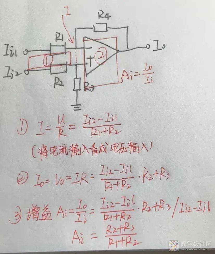
My operational amplifier calculation method is as follows: first, divide the circuit into two parts; the left part ① can calculate the current value, and the right part ② can calculate the total output voltage based on the current value calculated from ① using Ohm’s law, and finally calculate the amplification gain using the gain calculation formula.
3. In the middle is the operational amplifier’s unique function “virtual short,” so it can be viewed as a wire, which is equivalent to the common current value of parts ① and ②.
4. We can directly see that the current gain is determined by four resistors, so if you want to change the output size, you only need to change the corresponding resistor values.
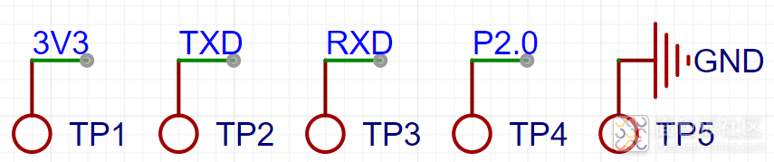
Factory Testing/Burning Points
By measuring the points with a multimeter, we can find TXD/RXD serial communication points, a data pin, and a power supply pin, indicating that these are likely factory burning/testing points.
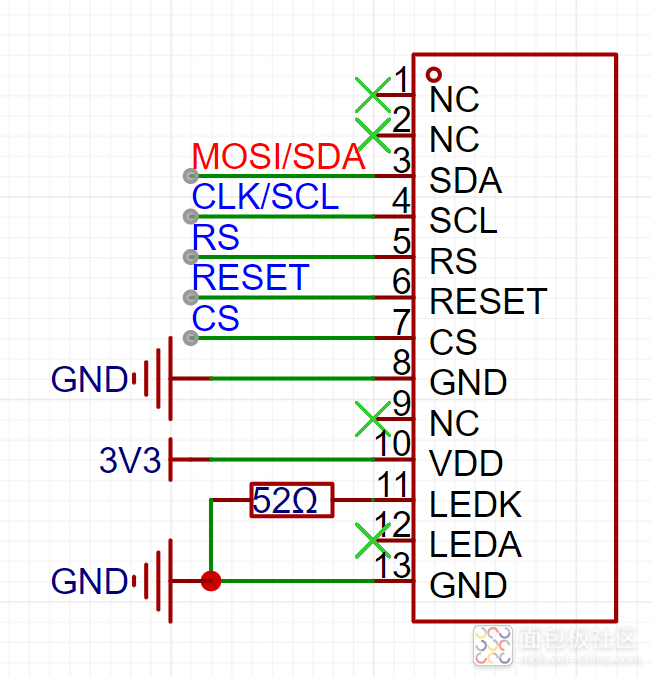
1. SDA—-SPI data line, connected to the MCU’s MOSI pin
2. SCL—-SPI serial clock line
3. RS—-Screen data, signal, command input selection
4. RESET—-Screen reset input
5. CS—-Screen chip select signal input
6. LEDK—-Backlight/cathode
[This MCU is speculative! If it differs from reality, please forgive! The focus is on learning]
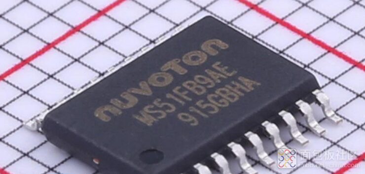
When observing the PCB, it is evident that the MCU has been polished, and after days of searching, I finally found an MCU that fits perfectly in terms of pins, functions, and size, which is likely the chip used in this power meter, very close!
1. First, I believe that if the chip has been polished off its silkscreen, it indicates that this MCU is likely not custom-made but rather a commonly used and cost-effective MCU available in the market, making it likely to be found.
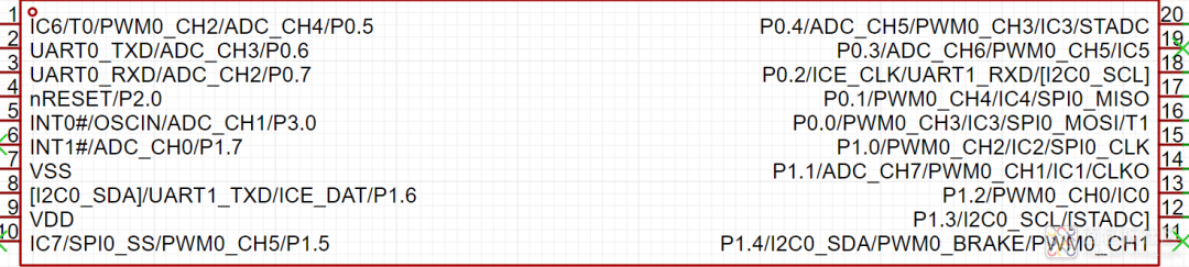
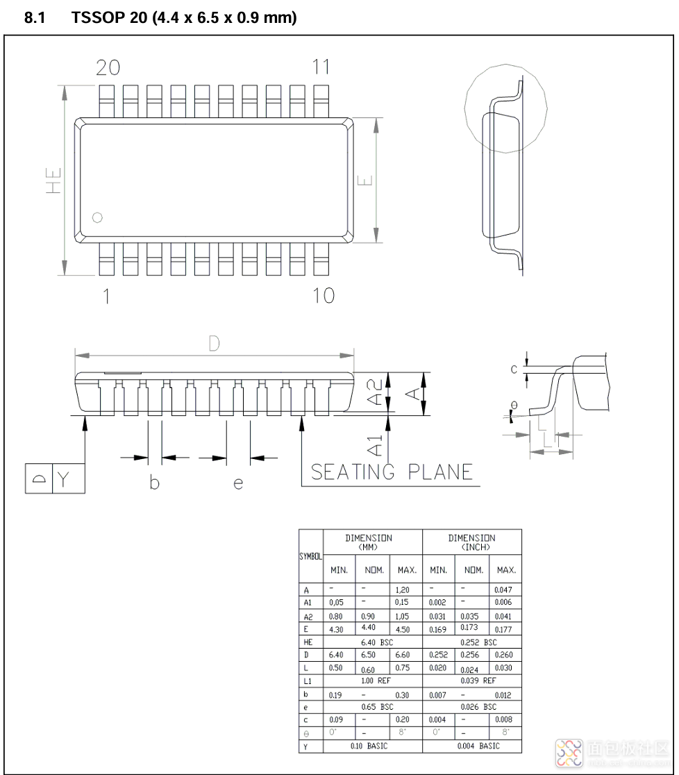
2. Observing the size, this MCU uses a TSSOP-20 package, which narrows down the search range a bit.
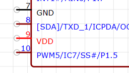
3. The best point of analysis is that the power supply pins are on pin 9 (VCC) and pin 7 (GND), a layout that is relatively rare. After looking at a dozen TSSOP-20 packaged chips, I finally found (Nuvoton) has such an MCU chip, and most layouts have pin 9 as VCC and pin 7 as GND.
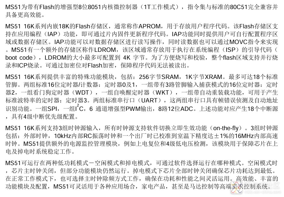
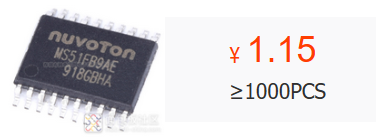
4. Thus, I looked for (Nuvoton) MCUs on the official website and various shopping platforms, as I determined this MCU has multiple ADC pins, serial communication, and SPI interface, which led me to find this model MS51FB9AE after searching through several options.
Data sheet: https://wwo.lanzouj.com/ixBZu1rfq07c
[The circuit diagram is obtained by measuring with a multimeter, and the resistance values may not be correct. Any issues can be discussed together.]
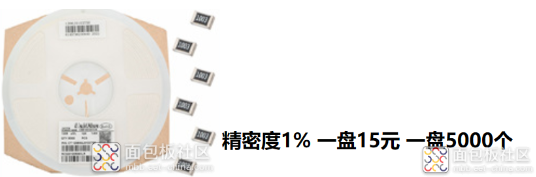
(1) A wholesale batch of 5000 resistors and capacitors costs about 15 yuan, approximately 0.003 each, totaling around 0.06.
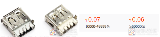
(2) USB male/female sockets wholesale for about 0.06 each, with two used per board, totaling 0.12.
(3) HT7133-1, output 3.3V, retail price 0.1 yuan, wholesale price unknown.
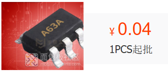
(4) LM321 operational amplifier, retail price 0.04 yuan.
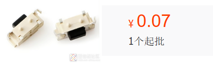
(5) Side-mounted tactile switch, retail price 0.07 yuan.
(6) MCU—-MS51FB9AE, retail price 1.2 yuan, wholesale 1.15.
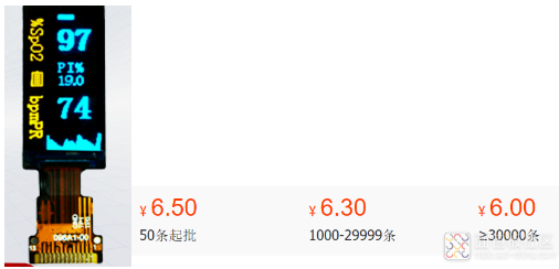
(7) TFT screen, size unknown, approximately 0.96, wholesale price 6 yuan.
(8) PCB board, price unknown, estimated at 0.5 each.
(9) The price of the shell is also unknown; assuming 0.5 each for two shells, that totals 1 yuan.
Hardware cost: 0.06 + 0.12 + 0.1 + 0.04 + 0.07 + 1.15 + 6 + 0.5 + 1 = 9.04
Software cost: 3, as the importance of software in this power meter is greater than that of hardware, and most technical costs are in software, so we estimate the software development cost for each meter at 3 yuan.
Other costs: 5, which include delivery, labor, operations, and other miscellaneous expenses, so we estimate 5 yuan here.
Total: 9.04 + 3 + 5 = 17.04
Compared to the selling price of 28 yuan, the vendor can probably earn around 10 yuan, making the profit quite considerable; I feel that most of the expenses are likely in software development!
(1) The principle of the power meter is to sample current and voltage and then calculate power. The difficulty in hardware lies in ensuring sampling accuracy, while the software difficulty lies in processing the received signals and obtaining values. Overall, a lot can be learned from this power meter.
(2) You can learn about operational amplifiers, understand their working process, and calculate amplification factors; as the first unit in analog electronics, their importance is significant.
(3) Analyzing costs shows that the required hardware cost for personal production is around 10 yuan, and the shell may be slightly more expensive. Therefore, it is feasible for anyone to make such a power meter themselves.
(4) Learning how to identify polished chips is very beneficial for circuit analysis.
Author: Breadboard Community Blogger Little Devil owo