
Recently, I have been learning about system porting. During the study and debugging process, I encountered many problems and solved many issues, yet I always had a vague feeling about our development results. Upon reflection, the main reason is that we do not have a deep understanding of our development environment. Sometimes, a few simple commands can accomplish very complex functions, but have we ever thought about why that is the case? If we do not ask questions and merely complete tasks mechanically while observing experimental results, we have not truly grasped the essence of system porting.

When performing each step, first ask yourself why you are doing this, then ask yourself what you are doing. Understanding these questions is crucial. No matter what platform, chip, or development environment you switch to in the future, you will not feel confused and will quickly get accustomed to it. My personal approach to learning embedded systems is to grasp the macro perspective (solving the ‘why’ question) and study the micro perspective (solving the ‘what’ question). Below, I will introduce my learning methods and experiences using the ARM Cortex-A8 development board as an example.
Porting Embedded Linux Systems consists of four main parts:
1. Setting up the cross-development environment2. Choosing and porting the bootloader3. Configuring, compiling, and porting the kernel4. Creating the root filesystemFirst part: Setting up the cross-development environment
Let’s first introduce the content of the first part: setting up the cross-development environment. First, we must think about two questions: What is a cross-environment? Why do we need to set up a cross-environment?
To answer the first question, cross-development is a crucial concept in embedded development. The first step is to set up the environment; if this step is not completed, the subsequent steps cannot proceed. The cross-development environment primarily refers to developing programs on the host machine (usually my PC) that can run on the target machine (usually our development board). Embedded systems are unique in that programs cannot be developed on the target machine (in a narrow sense) because a raw development board cannot run without any programs. To make it operational, we must use the PC to perform tasks such as programming, which allows the development board to run. This PC is what we refer to as the host machine. Consider that without the host machine, we would essentially be unable to develop for the target machine. This is also a famous saying in the electronics industry: “In electronics, it’s essentially about playing with computers!”
Now, to answer the second question, why do we need a cross-development environment? The main reasons are as follows:
Reason 1: Embedded systems have many hardware resource limitations, such as relatively low CPU clock speeds and small memory capacities. Imagine asking a few hundred MHz MCU to compile a Linux kernel—it would make us impatient. In contrast, a PC is faster and has more abundant hardware resources, thus using a PC for development will improve efficiency.
Reason 2: The MCU architecture and instruction set of embedded systems differ, so cross-compilation tools must be installed for compilation. This way, the compiled target program can run correctly on the respective platforms, such as ARM, MIPS, or PowerPC.
The hardware components of the cross-development environment mainly consist of the following:
1. Host machine2. Target machine (development board)3. Connection mediums between the two, commonly three types: (1) Serial cable (2) USB cable (3) Ethernet cable
In addition to the hardware mediums, corresponding software “mediums” are also necessary:
1. For serial connections, commonly used tools include serial debugging assistants, putty, etc. There are many tools with similar functionalities; knowing how to use one or two is sufficient;2. For USB cables, USB drivers are essential, typically provided by chip manufacturers. For example, for Samsung chips, USB downloads are mainly completed using DNW software;3. For Ethernet cables, network protocol support is necessary. The two main services are:
First: TFTP service:
It is mainly used to realize file downloads. For instance, during development and debugging, TFTP is used to download the bootloader, kernel, and filesystem directly into memory for execution without needing to pre-program them into the Flash chip. On one hand, frequent downloads often occur during testing; if each time we had to program these files into Flash and then run them, it would be cumbersome, and Flash has a limited number of erase cycles. On the other hand, since the purpose of testing is simply to load these target files into memory for direct execution, TFTP can exactly achieve this function, thus there is no need to program these files into Flash.
Second: NFS service:
It is mainly used to realize network file mounting, effectively achieving network file sharing. During development, typically in the last step of system porting, a filesystem is created. This can place the created filesystem in the appropriate location on our host PC, allowing the development board to mount it via NFS, thereby testing whether our created filesystem is correct. Throughout this process, there is no need to program the filesystem into Flash, and the mounting is done automatically. After the bootloader starts, the kernel runs and will automatically mount according to the startup parameters we set. Therefore, for development and testing, this method is very convenient and can significantly improve development efficiency.
Additionally, there is another service called Samba, which is also quite important, mainly for file sharing. The sharing mentioned here is not the same concept as NFS file sharing; NFS sharing achieves network file sharing, while Samba implements file sharing between a Windows host and a Linux virtual machine on the development host, facilitating file transfer.
The above several tools are essential for embedded development and have greatly contributed to improving development efficiency. Therefore, it is crucial to be proficient in using these tools, which will significantly enhance your development efficiency.Once testing is complete, the corresponding target files will be programmed into Flash, which is something done only when releasing products. Thus, for developers, all work is always about testing.
Through the previous work, we have prepared the hardware part of the cross-development environment and part of the software. Finally, we still lack a cross-compiler. Readers may wonder why we need to use a cross-compiler. As mentioned earlier, a cross-development environment will inevitably use cross-compilation tools, which can be simply understood as compiling a program that can run on a different architecture platform on one platform. For example, compiling on the host PC platform (X86 CPU) to produce a program that can run on an ARM-based CPU platform. The program compiled on the X86 CPU platform cannot run on the X86 CPU; it must be placed on the ARM CPU platform to run, even though both platforms use the Linux system. In contrast to cross-compilation, the usual compilation is called local compilation, which occurs on the current platform, and the compiled program is also executed locally. The compiler used for compiling such cross-platform programs is called a cross-compiler, while the tools used for local compilation are called local compilers. Therefore, to generate a program that runs on the target machine, it must be completed using a cross-compilation toolchain.
Here arises another question: isn’t it just a cross-compilation tool? Why is it called a cross-toolchain? The reason is simple: a program cannot just be compiled and run; it must also undergo the processes of assembly and linking, and debugging is also required. For a large project, engineering management is necessary, etc. Therefore, the cross-compilation tools referred to here constitute a comprehensive development environment composed of compilers, linkers, and interpreters. The cross-compilation toolchain mainly consists of three parts: binutils (which includes the assembler as and the linker ld), gcc (the GNU C compiler), and glibc (which defines some basic C functions and other functions). Sometimes, to reduce the size of the libc library, other C libraries can replace glibc, such as uClibc, dietlibc, and newlib.
So, how do we obtain a cross-toolchain? Is it simply a matter of downloading a “program” from the internet and installing it for use? Before answering this question, let’s consider another question: our cross-toolchain, as the name suggests, compiles programs that can run on our target development platform (for example, ARM) on the PC. But here comes another question: there are many models of ARM processors; is there a cross-toolchain specifically for each one? If there were, consider how many processor platforms there are. If a custom cross-toolchain were created for each platform and placed on the internet for everyone to download, it would take a long time to find the suitable compiler for your needs. Clearly, this approach is unreasonable and wastes resources! Therefore, to obtain a cross-toolchain, just like porting a Linux kernel, we only care about what we need and compile only the necessary components to run on our platform, excluding unnecessary components. Hence, the method of creating a cross-toolchain is very similar to system porting, meaning that the cross-development tools form a collection of tools that support many platforms (similar to Linux source code), and we only need to find the tools relevant to our platform from this tool collection. The question now is how to find the tools relevant to our platform; this involves how to create a cross-toolchain.
Typically, there are three methods to build a cross-toolchain:
Method 1: Step-by-step compilation and installation of the libraries and source code required for the cross-compilation toolchain, ultimately generating the cross-compilation toolchain. This method is relatively difficult and suitable for readers who want to delve into building cross-toolchains. If you just want to use a cross-toolchain, it is recommended to use the following Method 2.
Method 2: Using the Crosstool-ng script tool to achieve a one-time compilation to generate the cross-compilation toolchain. This method is much simpler than Method 1 and also has a very low chance of error, so it is recommended to use this method for building cross-compilation toolchains in most cases.
Method 3: Directly downloading an already made cross-compilation toolchain from the internet. The advantage of this method is straightforward and convenient, but it also has significant drawbacks, such as limitations. After all, it is built by someone else, which means it is fixed and lacks flexibility. Hence, the libraries and compiler versions used for building may not be suitable for the programs you want to compile, and you may encounter many inexplicable errors during use. Readers are advised to use this method with caution.
Crosstool-ng is a script tool that can create a suitable cross-compilation toolchain for different platforms. Before building, you need to install the following software: $ sudo apt-get install g++ libncurses5-dev bison flex texinfo automake libtool patch gcj cvs cvsd gawk. The crosstool script tool can be downloaded from http://ymorin.is-a-geek.org/projects/crosstool, then extracted. The configuration process is similar to configuring the kernel. The main steps are as follows: 1. Set the source package path and the installation path for the cross-compiler 2. Modify the architecture targeted by the cross-compiler 3. Increase the number of parallel processes during compilation to improve efficiency and speed up the compilation since this compilation will be relatively slow. 4. Disable the JAVA compiler to reduce compilation time 5. Compile 6. Add environment variables 7. Refresh environment variables. 8. Test the cross-toolchain.
At this point, the first part of the four major components of porting embedded Linux systems is complete. Next, we can proceed with subsequent development. Second part: Bootloader selection and porting
1. Boot Loader Concept
It is a small program that runs before the operating system kernel starts. Through this small program, we can initialize hardware devices, establish memory space mappings, thereby bringing the system’s software and hardware environment to a suitable state to prepare for the final invocation of the operating system kernel. This is what is known as the bootloader.
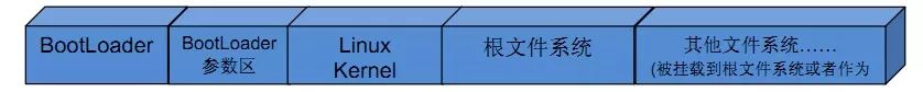
【Figure 1】 Distribution of files stored in Flash memory
2. Why port the BootLoader before system porting?
The task of the BootLoader is to boot the operating system. To boot the operating system means to start the kernel, which involves loading the kernel into memory (RAM) for execution. Now, let’s ask two questions: First, who moves the kernel into memory for execution? Second, we say that the memory is SDRAM. As we all know, this type of memory is different from SRAM; the main difference is that SRAM can run as long as the system is powered on, while SDRAM requires software initialization before it can run. Therefore, before moving the kernel into memory for execution, the memory must be initialized. Who is responsible for initializing the memory? In fact, both tasks are performed by the bootloader, aimed at preparing the software and hardware environment for the kernel’s operation. Without the bootloader, our system obviously cannot run.
3. Classification of bootloaders.
First, let’s correct a common misconception: many people say that the bootloader is U-boot. This statement is incorrect; to be precise, U-boot is a type of bootloader. In other words, there are many types of bootloaders, which can be roughly classified as shown in the figure below:
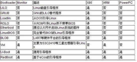
【Figure 2】 Bootloader classification diagram
As can be seen from the above figure, different bootloaders have different ranges of use, among which the most notable is a bootloader called U-Boot, which is a universal boot program that supports various processor architectures, including X86, ARM, and PowerPC. U-Boot, short for Universal Boot Loader, is an open-source project that follows the GPL terms, developed by the DENX group in Germany for various embedded CPUs. U-Boot has made significant contributions to Linux development, and it is open-source.
U-Boot has the following features:
① Open-source; ② Supports various embedded operating system kernels, such as Linux, NetBSD, VxWorks, QNX, RTEMS, ARTOS, and LynxOS; ③ Supports multiple processor families, such as PowerPC, ARM, x86, MIPS, and XScale; ④ High reliability and stability; ⑤ Highly flexible functionality settings, suitable for U-Boot debugging, different operating system boot requirements, product releases, etc.; ⑥ Rich device driver source code, such as serial ports, Ethernet, SDRAM, FLASH, LCD, NVRAM, EEPROM, RTC, keyboards, etc.; ⑦ Relatively rich development debugging documentation and strong network technical support; In fact, U-Boot can be understood as a small operating system.
4. Directory structure of U-Boot
* board: Files related to the target board, mainly including SDRAM and FLASH drivers; * common: General code independent of processor architecture, such as memory size detection and fault detection; * cpu: Files related to the processor. For example, the mpc8xx subdirectory contains files for serial ports, network ports, LCD drivers, and interrupt initialization; * driver: General device drivers, such as CFI FLASH drivers (currently, there is good support for INTEL FLASH); * doc: Documentation for U-Boot; * examples: Example programs that can run under U-Boot, such as hello_world.c, timer.c; * include: U-Boot header files; especially the configuration header files related to the target board in the configs subdirectory, which are often modified during the porting process; * lib_xxx: Files related to processor architecture, such as lib_ppc, lib_arm directories containing files related to PowerPC and ARM architectures respectively; * net: Files related to network functions, such as bootp, nfs, tftp; * post: Power-on self-test file directory, which is yet to be improved; * rtc: RTC driver; * tools: Tools for creating U-Boot S-RECORD and BIN image files; 5. U-Boot working modes
The working modes of U-Boot include boot loading mode and download mode. The boot loading mode is the normal working mode of the Bootloader, and when embedded products are released, the Bootloader must operate in this mode, loading the embedded operating system from FLASH into SDRAM for execution. This entire process is automatic. The download mode is where the Bootloader downloads the kernel image or root filesystem image from the PC into the target board’s SDRAM for execution. Users can utilize some command interfaces provided by the Bootloader to perform their desired operations. This mode is mainly used for testing and development.
6. U-Boot startup process
Most BootLoaders are divided into two main parts: stage1 and stage2, and U-Boot is no exception. The CPU architecture-dependent code (such as device initialization code) is usually placed in stage1 and can be implemented in assembly language, while stage2 is typically implemented in C language, allowing for more complex functionalities with better readability and portability.
1. Stage1 (start.s code structure): The stage1 code of U-Boot is usually found in the start.s file, which is written in assembly language. The main parts of the code are as follows: (1) Define the entry point. Since an executable image must have a single global entry point, usually placed at address 0x0 in ROM (Flash), the compiler must be notified to make it aware of this entry, which can be accomplished by modifying the linker script. (2) Set the exception vector. (3) Set the CPU speed, clock frequency, and interrupt control registers. (4) Initialize the memory controller. (5) Copy the program from ROM to RAM. (6) Initialize the stack. (7) Jump to execute in RAM, which can be accomplished using the ldrpc instruction.
2. Stage2 (C language code part)
The start armboot function in lib_arm/board.c is the C language entry point and serves as the main function of the entire boot code. This function primarily performs the following operations: (1) Calls a series of initialization functions. (2) Initializes the flash device. (3) Initializes the system memory allocation functions. (4) If the target system has NAND devices, it initializes the NAND device. (5) If the target system has display devices, it initializes these devices. (6) Initializes related network devices, filling in IP addresses, etc. (7) Enters the command loop (the entire boot working loop), accepting user commands from the serial port and executing corresponding tasks.
7. Analysis of S5PC100 bootloader startup process based on Cortex-A8
S5PC100 supports two boot methods: USB boot method and NAND Flash boot method:
1. S5PC100 USB boot process
[1] A8 reset, executing the program in iROM. [2] The program in iROM initializes USB based on the configuration pins of S5PC100 (SW1 switch 4, set to the opposite side of 4), determining where to boot from (USB). [3] The program in iROM will initialize USB and wait for the PC to download the program. [4] Using the DNW program, download the SDRAM initialization program from the PC to iRAM for execution, initializing SDRAM. [5] After SDRAM initialization is complete, the program in iROM continues to take over A8 and waits for the PC to download the BootLoader. [6] The PC uses DNW to download BootLoader to SDRAM. [7] BootLoader runs in SDRAM.
2. S5PC100 NAND Flash boot process
[1] A8 reset, executing the program in IROM. [2] The program in iROM drives NAND Flash based on the configuration pins of S5PC100 (SW1 switch 4, set to the side close to 4). [3] The program in iROM copies the first 16k from NAND Flash to iRAM. [4] The first 16k program (the first half of the BootLoader) initializes SDRAM, then copies the complete BootLoader to SDRAM and runs it. [5] The BootLoader copies the kernel to SDRAM and runs it. [6] Once the kernel runs, it mounts the rootfs and executes the system initialization script.
8. U-Boot porting (taking S5PC100 based on Cortex-A8 as an example)
1. Establish your platform
(1). Download the source package version 2010.03, which is relatively stable. (2). After extracting, add your platform information, using smdkc100 as a reference to port your S5PC100 development board. (3). Modify the corresponding directory filenames and the necessary Makefile to specify the cross-toolchain. (4). Compile. (5). Port accordingly to your platform, mainly including modifying the SDRAM running address from 0x20000000 (6). “Switch” corresponding macro definitions. (7). Add NAND and network card driver code. (8). Optimize the go command. (9). Recompile make distclean (completely delete intermediate files and configuration files) make s5pc100_config (configure your development board) make (compile out your u-boot.bin image file). (10). Set environment variables, i.e., startup parameters, to download the compiled U-Boot into memory for execution. The process is as follows: 1. Configure the development board network ip address configuration: $setenv ipaddr 192.168.0.6 set the IP address to the memory environment variable $saveenv save the environment variable value to the NAND Flash parameter area network test: ping the virtual machine on the development board: $ ping 192.168.0.157 (the virtual machine’s IP address) If the network test fails, check the network from the following aspects: 1. Ensure the network cable is connected properly 2. Ensure the IP addresses of the development board and virtual machine are configured on the same subnet 3. Ensure the virtual machine network is set to bridge mode (VM–Setting–>option) 4. When connecting to the development board, the virtual machine needs to be set to static IP address 2. On the development board, configure the IP address of the TFTP server (virtual machine) $setenv serverip 192.168.0.157 (virtual machine’s IP address) $saveenv 3. Copy u-boot.bin to /tftpboot (the directory on the virtual machine) 4. Use TFTP to download u-boot.bin into the development board’s memory $ tftp 20008000 (memory address) u-boot.bin (file name to download) If the above command fails to download properly: 1. Check if serverip is configured correctly 2. Restart the TFTP service if it fails to start #sudo service tftpd-hpa restart 5. Write u-boot.bin to NAND Flash starting from address 0 $nand erase 0 (starting address) 40000 (size) erase the NAND Flash area from 0 – 256k $nand write 20008000 (the cached memory address of u-boot.bin) 0 (the location of u-boot on NAND Flash) 40000 (write size) 6. Switch the development board’s boot method to NAND Flash 1. Power off the development board 2. Set switch 4 of SW1 to the side of 4 3. Power on the development board to boot from NAND Flash Third part: Kernel configuration, compilation, and porting
1. Copy the downloaded linux-2.6.35.tar.bz2 to the home directory and extract it
2. Modify the Makefile in the top-level directory, mainly modifying the platform architecture and cross-compiler. The code is as follows:
ARCH ?= $(SUBARCH) CROSS_COMPILE ?= CROSS_COMPILE ?= $(CONFIG_CROSS_COMPILE:”%”=%) Modify the above code to: ARCH ?= arm —-> architecture is ARM CROSS_COMPILE ?= arm-cortex_a8-linux-gnueabi- —-> cross-compiler is for ARM Cortex-A8 platform Note: These two variable values will directly affect the compilation behavior of the top-level Makefile, namely which code to compile and what compiler to use for compilation.
3. Copy the standard configuration file to obtain configuration information related to our development board.
$ cp arch/arm/configs/s5pc100_defconfig .config
Here, copying arch/arm/configs/s5pc100_defconfig to .config selects the code related to our development board. Since Linux supports an extremely large number of platforms, not just ARM processors, we only need to compile the code related to our platform during compilation; the platform-related code does not need to be compiled. This raises the question: Linux source code files number in the billions. How do we choose from such a vast quantity of files?
In fact, the concern we have was already addressed by the folks who wrote the operating system. They have solved this problem for us. We only need to perform a simple operation to select the code we want to compile. The specific method is to copy the corresponding platform’s _defconfig directly to the .config file in the top-level directory. This way, the .config file records the platform information related to the platform we are porting, as the system will store all configuration information in the .config file during kernel configuration. Note that the first time you run make menuconfig, the system will automatically select relevant code and modules based on the platform information you choose. Thus, you only need to enter and exit, choose to save the configuration information, and the system will save all configuration information related to the platform we are porting in the .config file in the top-level directory.
4. Configure the kernel
$make menuconfig
Note: The first time you enter, do not perform any operations; just exit. When prompted to save configuration information, be sure to save it by clicking “YES.” This way, our .config already contains the information about our development platform.
In this stage, we need to pay attention to one question: what does the system do when executing make menuconfig? Why does a graphical interface appear? Where does the content in the graphical interface come from?
The graphical interface is implemented by a special graphical library. Remember that the first time you run make menuconfig, the system did not show a graphical interface but instead reported an error indicating that we were missing ncurses-devel. At this point, we only need to install libncurses5-dev, sudo apt-get install libncurses5-dev. With this graphical library’s support, we can display the graphical interface normally.
Now that the graphical interface issue is resolved, there is another question: where does the content in the graphical interface come from? To answer this question, we need to mention the design philosophy of the Linux kernel. The Linux kernel is organized in a modular fashion. But why use a modular approach? What is the concept of modules? Here, I will answer these questions one by one.
In the source tree directory of the Linux 2.6 kernel, there are generally two files: Kconfig and Makefile. The Kconfig files distributed across various directories form a distributed kernel configuration database, with each Kconfig describing the configuration menu related to the source files in that directory. Each directory stores relatively independent information, and each directory contains various module information. For example, in the /dev/char/ directory, all character device drivers are stored, and these program codes exist in the kernel in the form of modules. This means that when the system needs a driver, it will compile it into the kernel as a module. The compilation can be static or dynamic; static compilation results in a larger kernel size than dynamic compilation. As previously mentioned, each directory contains a Kconfig file. You may ask what information is stored in this file. Each Kconfig file describes the configuration menu related to the source files in its directory and has its specific syntax format. The text in the graphical interface is read from this file. Therefore, if you delete the relevant information from this file, you will not see that module’s information in the graphical interface and will not be able to configure that module.
When configuring the kernel using make menuconfig (or xconfig, etc.), the system automatically reads the configuration menus from Kconfig, and after the user configures and saves it, the information is stored in .config (generated in the top-level directory). During kernel compilation, the main Makefile calls this .config, and the importance of .config lies in that it saves all our configuration information, serving as the final basis for selecting source code and compiling it!!!
The above content indicates that Kconfig corresponds to the kernel configuration menu. If you want to add a new driver to the kernel source, you can modify Kconfig to increase the configuration menu for your driver. This way, you can select your driver. If you want that driver to be compiled, you also need to modify the Makefile in the directory where the driver is located. Therefore, generally, when adding a new driver, the files that need to be modified include two types: Kconfig and the corresponding directory’s Makefile (Note: Not just these two!). A significant part of system porting is adding and removing relevant modules from the kernel, so the main files that need to be modified in the kernel are Kconfig and the corresponding directory’s Makefile.
5. Compile the kernel
$make zImage
Through the above operations, we can generate a zImage file in the arch/arm/boot directory, which is the compressed kernel image.
The kernel compilation process is very complex. Note that this compilation is static compilation, and during this process, the zImage command in the top-level directory’s Makefile will be executed, selecting source code for compilation based on the .config file. The specific steps for compiling the kernel are quite complicated, and I will write another article to describe them in detail when time permits. 6. Download and test the kernel through TFTP network service
setenv bootcmd tftp 20008000 (memory address) zImage; go 20008000 setenv bootargs nfs nfsroot=192.168.1.199 (virtual machine’s IP):/source/rootfs ip=192.168.1.200 (development board’s IP) init=/linuxrc (the first user process to start) ttySAC0,115200 (set the interrupt to serial port 1, baud rate: 115200)
Save the environment variables, reset the development board, and test whether it can start normally (Note: before this, the filesystem to be mounted via NFS should be set up properly to see the effect). The kernel testing and startup process is also quite complex, which will be detailed in subsequent articles. Fourth part: Introduction to the root filesystem
From the first image of this article: Distribution of files stored in Flash memory, it can be seen that the creation and porting of the filesystem is the final step of system porting. Here, I would like to raise a few questions: 1.What is a filesystem? 2.How to implement a filesystem? 3.What are the commonly used filesystems? Why are these filesystems needed?
Now, let’s answer these questions one by one:
We rarely hear the term filesystem in our daily lives, but it certainly exists; it just goes by a different name, usually referred to as a database. A database contains numerous files, and how do we quickly and accurately find the file we need? The database employs a classification index method to achieve fast searches, similar to how our school library is managed. The first floor might be for philosophy, the second for social sciences, the third for electronics, the fourth for computer science, and so on. We call this categorized index database a filesystem.
For computers, files are actually data that can only be stored on physical media like hard drives. However, we cannot read files directly from physical media or write files to physical media ourselves; reading and writing files on physical media can only be accomplished through programs. To facilitate this, programs are divided into physical medium driver programs, content storage programs, and file content storage programs. Physical medium driver programs are specifically used for accessing data from physical media; content storage programs package file content and file attribute information; file content storage programs take user input to form file content or retrieve file content for display.
We can decompose a filesystem (inverted tree) into multiple filesystems (inverted tree) stored on different storage media. For example, one is stored on a CD, and another is stored on a hard drive. When in use, we can mount the root directory of the filesystem on the CD to a directory on the hard disk filesystem, allowing access to that directory to be equivalent to accessing the root directory of the CD. Once we find the root directory, we can access the entire filesystem on the CD.
The statement, “In Linux, everything is a file,” is often heard when learning Linux. Although somewhat exaggerated, it reveals the importance of the filesystem to the Linux system. In fact, filesystems are crucial for all operating systems because they manage most hardware devices and software data in the form of files.The management framework for devices and data in the Linux system is shown below:
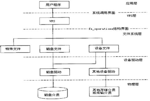
【Figure 3】 Filesystem implementation
[Explanation]
A. VFS (virtual file system) manages special files (virtual files), disk files, and device files.
B. The fs_operations structure consists of a series of file operation interface functions completed by the filesystem layer to provide file operations for VFS;
C. At the filesystem layer, disk files must implement various filesystems (such as: ext2), and device files must implement various abstract device drivers.
D. At the device driver layer, disk drivers must implement various disk driver programs, while other device drivers must implement specific device drivers.
E. The physical layer is the device itself.
Why are there different file types?
Due to the existence of many types of storage media, it is impossible to use a single unified format to store the filesystem on various different storage media. Instead, multiple different storage formats are needed to adapt to the characteristics of various storage media to optimize access efficiency and space utilization, necessitating the establishment of specifications for each storage format, which are referred to as filesystem types. Common filesystem types include: 1. DOS FAT16, 2. Windows FAT16, FAT32, NTFS 3. Linux Minix, ext, ext2, ext3, ISO9660, jffs2, yaffs, yaffs2, cramfs, romfs, ramdisk, rootfs, proc, sysfs, usbfs, devpts, tmpfs & ramfs, NFS
As can be seen, Linux supports the most filesystems. They can be classified by different media as follows:? Disk: FAT16, FAT16, FAT32, NTFS, ext, ext2, ext3, Minix? CD: ISO9660? Flash: jffs2, yaffs, yaffs2, cramfs, romfs? Memory: Ramdisk, tmpfs & ramfs? Virtual: rootfs, proc, sysfs, usbfs, devpts, NFS
In theory, commonly used storage media can store Linux supported filesystems; however, since we are only studying embedded systems, and due to the size and mobility characteristics of embedded systems, we cannot use disks and CDs, so we must use flash-type storage devices, memory, and virtual storage devices as the storage medium for the filesystem.
The driver program for flash chips is provided by the system, so its access characteristics are entirely based on the characteristics of the flash itself. It is best to have a filesystem specifically suited for flash—Jffs, Yaffs, Cramfs, and Romfs. These filesystems are commonly used in embedded Linux systems, and they can be selected based on their characteristics. Their characteristics are as follows: Common pointsBased on MTD driverJffs A. Implemented for NOR Flash B. A log-structured filesystem based on hash tables C. Employs wear-leveling technology to ensure that write positions are evenly distributed during each write D. Readable and writable, supports data compression E. Provides crash/power-off safety protection F. When the filesystem is full or nearly full, the running speed significantly slows down due to garbage collection Yaffs A. Implemented for NAND Flash B. A log-structured filesystem C. Employs wear-leveling technology to ensure that write positions are evenly distributed during each write D. Readable and writable, does not support data compression E. Short mount time, occupies little memory F. Comes with NAND flash drivers, can operate without using VFS and MTD Cramfs A. Single-page compressed, supports random access, achieving compression ratios of up to 2:1 B. Fast speed, high efficiency C. Read-only, which helps protect the filesystem from damage, improving system reliability, but cannot expand its content Romfs A. Simple, compact, read-only filesystem B. Stores data sequentially, thus supporting applications to run in XIP (execute In Place) mode, saving RAM space during system operation Specific filesystem types:Ramdisk filesystem
In the Linux system, memory is often used to store filesystems, referred to as Ramdisk. There are two types of Ramdisk: one treats memory as a physical storage medium, simulating a disk using memory, employing the disk’s filesystem type; the other only stores the logical structure of the filesystem in memory, using tmpfs & ramfs filesystem types: tmpfs & ramfs
1. Overview Treats physical memory as a disk partition; once this partition is mounted, files can be read and written just like disk files, but the operation speed is much faster than that of disk files. Therefore, it is generally applied in the following areas: 1) Files requiring fast read and write speeds should be placed in this filesystem 2) In the case of flash disk partitioning, frequently read and written files should be placed in this filesystem and periodically written back to flash 3) Temporary files in the system, such as those in the /tmp and /var directories, should be placed in this filesystem 4) /dev device files (since device files change with the loading and unloading of drivers and devices) should be placed in this filesystem
2. Characteristics 1) Since data is stored in physical memory, all data in this filesystem will be lost after the system reboots. 2) Ramfs will automatically grow in size if no maximum size is specified, consuming all physical memory, potentially causing system crashes; it is advisable to limit its maximum size when mounting. 3) If a size is specified for tmpfs, it will grow to that size, and the system will limit its size; the physical memory pages occupied by this filesystem can be swapped to the swap partition, but Ramfs cannot.
Different filesystems have different production methods, some are relatively complex, while others are simpler. Due to space limitations, I will not introduce them here; I will separately discuss the creation of filesystems in future articles.
END
Official Site: www.linuxprobe.com
Linux Command Collection: www.linuxcool.com
Teacher Liu Chuan’s QQ: 5604922
Linux Technology Exchange Group: 193666693
(New group, hotly adding members…)
Readers who want to learn the Linux system can click the “Read Original” button to learn about the book “Learning Linux This Way,” which is also very suitable for professional operation and maintenance personnel to read, becoming a high-value tool for assisting your work!