
Click the “Embedded Miscellaneous” above to select “Top Official Account” to view embedded notes at the first time!

Source: http://www.ruanyifeng.com/blog
Learning programming is actually about learning high-level languages, which are computer languages designed for humans.
However, computers do not understand high-level languages; they must be converted into binary code by a compiler to run. Knowing a high-level language does not equate to understanding the actual steps taken by the computer.
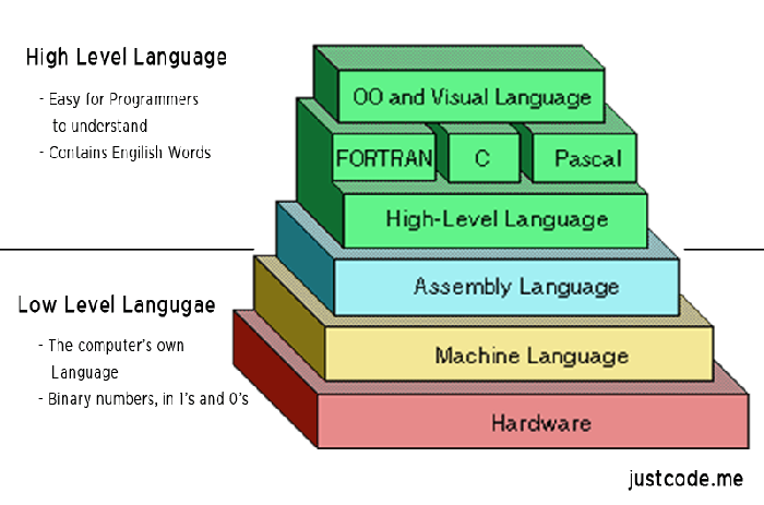
The only language that computers can truly understand is low-level language, which is used to control hardware. Assembly language is a low-level language that directly describes/controls the CPU’s operation. If you want to understand what the CPU is actually doing and the steps of code execution, you must learn assembly language.
Assembly language is not easy to learn, and even concise introductions are hard to find. Below, I will attempt to write the easiest-to-understand assembly language tutorial, explaining how the CPU executes code.

1. What is Assembly Language?
We know that the CPU is only responsible for computation and lacks intelligence. When you input an instruction, it executes it once, then stops and waits for the next instruction.
These instructions are all binary, known as operation codes (opcode). For example, the addition instruction is 00000011. The role of the compiler is to translate the program written in high-level language into a series of operation codes.
For humans, binary programs are unreadable; we can’t see what the machine is doing. To solve the readability issue and occasional editing needs, assembly language was born.
“Assembly language is the textual form of binary instructions”, corresponding one-to-one with the instructions. For example, the addition instruction 00000011 is written in assembly language as ADD. As long as it is converted back to binary, assembly language can be directly executed by the CPU, making it the lowest-level low-level language.
2. Origin
In the early days, writing programs involved manually writing binary instructions and inputting them into the computer through various switches. For example, to perform addition, one would press the addition switch. Later, the paper tape punch was invented, allowing binary instructions to be automatically input into the computer by punching holes in a paper tape.
To address the readability of binary instructions, engineers wrote those instructions in octal. Converting binary to octal is easy, but the readability of octal is also poor.
Naturally, it eventually returned to using text, with the addition instruction written as ADD. Memory addresses were no longer directly referenced but represented using labels.
This added an extra step, which is to translate these text instructions into binary. This step is called assembling, and the program that completes this step is called an assembler. The text it processes is naturally called assembly code. After standardization, it is referred to as assembly language, abbreviated as asm, translated into Chinese as 汇编语言.
Each CPU has different machine instructions, so the corresponding assembly language is also different. This article introduces the most common x86 assembly language, which is used by Intel’s CPUs.
3. Registers
To learn assembly language, one must first understand two concepts: registers and memory models.
First, let’s look at registers. The CPU is responsible for computation but not for storing data. Data is generally stored in memory, and the CPU reads and writes data from memory when needed.
However, the CPU’s computation speed is much faster than the read and write speed of memory. To avoid being slowed down, the CPU comes with Level 1 and Level 2 caches. Essentially, CPU caches can be seen as faster memory for reading and writing.
However, CPU caches are still not fast enough, and the addresses of data in the cache are not fixed, meaning that the CPU has to address each read and write operation, which can also slow down speed.
Therefore, in addition to caches, the CPU also has registers to store the most frequently used data. This means that the most frequently read and written data (such as loop variables) will be placed in registers, and the CPU will prioritize reading and writing registers before exchanging data with memory.
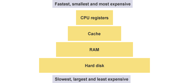
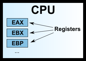
Registers do not distinguish data by address but by name. Each register has its name, and we tell the CPU which specific register to fetch data from, making this the fastest method. Some compare registers to the CPU’s zero-level cache.
4. Types of Registers
Early x86 CPUs had only 8 registers, each with different purposes. Now, there are over 100 registers, which have become general-purpose registers without specific assignments, but the names of the early registers have been preserved.
-
EAX -
EBX -
ECX -
EDX -
EDI -
ESI -
EBP -
ESP
Among these 8 registers, the first seven are general-purpose. ESP register has a specific purpose of storing the address of the current Stack (see the next section).
We often see names like 32-bit CPU or 64-bit CPU, which actually refer to the size of the registers. A 32-bit CPU has a register size of 4 bytes.
5. Memory Model: Heap
Registers can only hold a small amount of data, and most of the time, the CPU needs to direct registers to exchange data directly with memory. Therefore, in addition to registers, it is essential to understand how memory stores data.
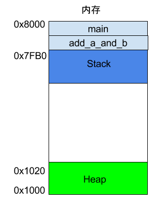
When a program runs, the operating system allocates a segment of memory to store the program and the data generated during execution. This memory has a starting address and an ending address, such as from 0x1000 to 0x8000, where the starting address is the smaller address and the ending address is the larger one.

During program execution, for dynamic memory allocation requests (such as creating new objects or using the malloc command), the system will allocate a portion of the pre-allocated memory to the user, specifically starting from the starting address (in reality, the starting address will have a segment of static data, which we will ignore here).
For example, if the user requests 10 bytes of memory, it will be allocated from the starting address 0x1000 to address 0x100A. If another request for 22 bytes is made, it will be allocated to 0x1020.
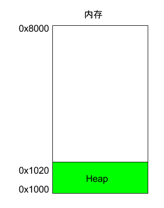
This memory area allocated due to user requests is called Heap. It grows from the starting address upwards (to higher addresses). One important characteristic of the Heap is that it does not disappear automatically; it must be manually released or reclaimed by a garbage collection mechanism.
6. Memory Model: Stack
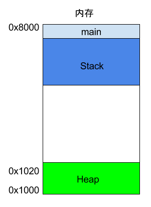
Aside from the Heap, other memory usage is called Stack. Simply put, the Stack is the memory area temporarily occupied by function execution.

Let’s look at the example below.
int main()
{
    int a = 2;
    int b = 3;
}
In the code above, when the system starts executing the main function, it will create a frame in memory for it, where all internal variables of main (such as a and b) are stored. After the main function finishes executing, this frame will be reclaimed, freeing all internal variables and no longer occupying space.
If a function calls another function, what happens?
int main()
{
   int a = 2;
   int b = 3;
   return add_a_and_b(a, b);
}
In the code above, the main function calls the add_a_and_b function internally. When executing this line, the system will also create a new frame for add_a_and_b to store its internal variables. This means that at this point, there are two frames simultaneously: main and add_a_and_b. Generally, the number of frames in the call stack corresponds to the number of layers in function calls.
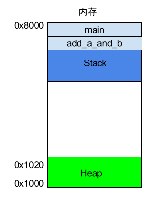
When add_a_and_b finishes executing, its frame will be reclaimed, and the system will return to the point where the main function was interrupted, continuing execution. This mechanism allows for layered function calls, with each layer able to use its local variables.
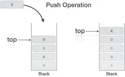
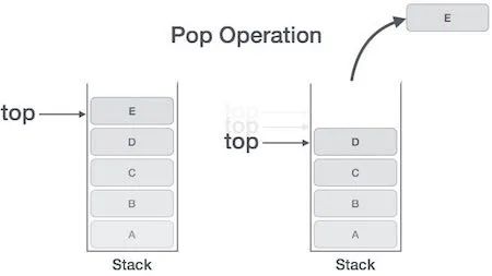
All frames are stored in the Stack. Since frames are stacked on top of each other, the Stack is called a stack. Creating a new frame is called “pushing onto the stack”; in English, it is called push; reclaiming the stack is called “popping off the stack”; in English, it is called pop. The characteristic of the Stack is that the last frame pushed onto the stack is the first one to be popped off (because the innermost function call ends first), which is called “last in, first out” data structure.
Every time a function finishes executing, a frame is automatically released, and when all functions finish executing, the entire Stack is released.
The Stack is allocated from the end address of the memory area, starting from high addresses downwards. For example, if the end address of the memory area is 0x8000, the first frame is assumed to be 16 bytes, so the next allocation will start from 0x7FF0; if the second frame is assumed to need 64 bytes, the address will move to 0x7FB0.
7. CPU Instructions
7.1 An Example
Once you understand registers and memory models, you can see what assembly language actually is. Below is a simple program example.c.
int add_a_and_b(int a, int b) {
   return a + b;
}

int main() {
   return add_a_and_b(2, 3);
}
gcc will convert this program into assembly language.
$ gcc -S example.c
After executing the command above, a text file example.s will be generated, containing assembly language with dozens of lines of instructions. To put it this way, a simple operation in a high-level language may consist of several, or even dozens of CPU instructions at the lower level. The CPU executes these instructions sequentially to complete this operation.
example.s simplified looks something like this.
_add_a_and_b:
   push   %ebx
   mov    %eax, [%esp+8]
   mov    %ebx, [%esp+12]
   add    %eax, %ebx
   pop    %ebx
   ret

_main:
   push   3
   push   2
   call   _add_a_and_b
   add    %esp, 8
   ret
As you can see, the two functions in the original program add_a_and_b and main correspond to two labels _add_a_and_b and _main. Each label contains the CPU execution flow for that function.
Each line represents a single operation executed by the CPU. It can be divided into two parts, taking one line as an example.
push %ebx
In this line, push is the CPU instruction, and %ebx is the operand used by this instruction. A CPU instruction can have zero or more operands.
Next, I will explain this assembly program line by line, and I suggest readers copy this program into another window to avoid scrolling back up while reading.
7.2 Push Instruction
According to convention, the program starts executing from the _main label, at which point a frame will be created on the Stack for main, and the address pointed to by the Stack will be written into the ESP register. If data needs to be written to the main frame, it will be written at the address stored in the ESP register.
Then, execution begins with the first line of code.
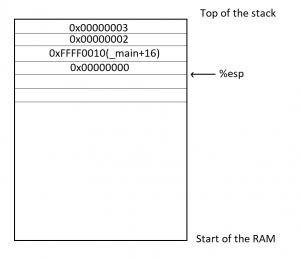
push 3
The push instruction is used to place the operand onto the Stack, in this case, writing 3 into the main frame.
Although it looks simple, the push instruction actually has a preceding operation. It first retrieves the address in the ESP register, subtracts 4 bytes from it, and then writes the new address back into the ESP register.
The subtraction is because the Stack grows downwards, and 4 bytes is because 3 is of type int, which occupies 4 bytes. After obtaining the new address, 3 will be written to the starting four bytes of this address.
push 2
The second line is the same, where the push instruction writes 2 into the main frame, right next to where 3 was written. At this point, the ESP register will again subtract 4 bytes (a total of 8 bytes subtracted).
7.3 Call Instruction
The third line’s call instruction is used to call a function.
call _add_a_and_b
The code above indicates a call to the add_a_and_b function. At this point, the program will look for the _add_a_and_b label and create a new frame for that function.
Next, it will begin executing the code of _add_a_and_b.
push %ebx
This line indicates that the value in the EBX register is written to the _add_a_and_b frame. This is because this register will be used later, so its value is saved and will be written back after use.
At this point, the push instruction will also subtract 4 bytes from the address in the ESP register (a total of 12 bytes subtracted).
7.4 Mov Instruction
The mov instruction is used to write a value into a specific register.
mov %eax, [%esp+8]
This line of code indicates that the address in the ESP register is incremented by 8 bytes to obtain a new address, then the data at this address is retrieved from the Stack. Based on previous steps, it can be inferred that the value retrieved here is 2, which is then written into the EAX register.
The next line of code does the same thing.
mov %ebx, [%esp+12]
The code above retrieves the value at the address in the ESP register incremented by 12 bytes, which is 3, and writes it into the EBX register.
7.5 Add Instruction
The add instruction is used to add two operands and write the result into the first operand.
add %eax, %ebx
The code above adds the value in the EAX register (which is 2) to the value in the EBX register (which is 3), obtaining the result 5, which is then written back to the first operand, the EAX register.
7.6 Pop Instruction
The pop instruction is used to retrieve the most recently written value from the Stack (i.e., the value at the lowest address) and write it to the location specified by the operand.
pop %ebx
The code above indicates that the most recently written value from the Stack (i.e., the original value of the EBX register) is retrieved and written back to the EBX register (since the addition is complete and the EBX register is no longer needed).
Note that the pop instruction will also add 4 bytes to the address in the ESP register, effectively reclaiming 4 bytes.
7.7 Ret Instruction
The ret instruction is used to terminate the execution of the current function and return control to the calling function. In other words, the current function’s frame will be reclaimed.
ret
As you can see, this instruction has no operands.
With the termination of the add_a_and_b function, the system returns to the point where the main function was interrupted, continuing execution.
add %esp, 8
The code above indicates that the address in the ESP register is manually incremented by 8 bytes and written back to the ESP register. This is because the ESP register points to the starting address of the Stack, and the previous pop operation has already reclaimed 4 bytes, so this operation reclaims 8 bytes, effectively reclaiming all.
ret
Finally, the main function ends execution, and the ret instruction exits the program.
8. Reference Links
-
Introduction to reverse engineering and Assembly, by Youness Alaoui -
x86 Assembly Guide, by University of Virginia Computer Science
Friendly Reminder
Due to recent changes in the WeChat public account’s push rules, if you want to see our articles frequently, you can click “Like” or “View” at the bottom of the page after reading each time, so that the articles pushed each time will appear in your subscription list at the first time.
Copyright Notice: This article is sourced from the internet, freely conveying knowledge, and the copyright belongs to the original author. If there are any copyright issues regarding the works, please contact me for deletion.
You may also like:
Selected Articles from Embedded Miscellaneous
Step-by-step Guide to Using VSCode + gdb + gdbserver to Debug ARM Programs
Domestic Conscience Tool – FinalShell
Share 10 Interesting C Language Interview Questions and Answers
A Summary Review of WiFi Driver Porting
Reply 1024 in the public account chat interface to get embedded resources; reply m to view article summaries.
You have finished reading the article Don’t you want to click an
  ?
?