
Click the blue text to follow us

When developing hardware designs, three types of boards are commonly used: breadboards, perfboards, and PCBs. What are these three types of boards, and which one should be used at different stages of hardware development? Today, let’s clarify these questions all at once.
 1
1
Breadboard
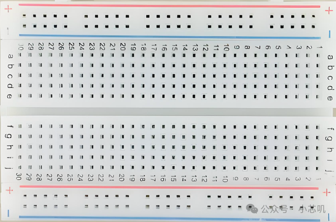
Breadboard
A breadboard is a circuit board designed for non-soldering experimental circuit design. The board has many holes where we can insert components such as development boards, resistors, capacitors, and diodes to quickly connect circuits, and we can also move the components’ positions at any time.
Common breadboard sizes include 170 holes, 400 holes, and 830 holes. When building circuits for complex projects, multiple breadboards can be connected using clips or jumper wires to expand into a larger breadboard, thereby increasing the experimental area.

Connection relationship of the rows and holes on the breadboard
The red and blue lines on the sides of the breadboard correspond to the positive and negative terminals (the red line corresponds to the positive terminal, and the blue line corresponds to the negative terminal). The middle part is usually used to build circuits,the five holes in the same row are interconnected.
There are column labels a-j and row labels with numbers on the breadboard, where the numbers depend on the length of the breadboard. These labels allow us to quickly locate when constructing circuits.
Breadboards are suitable for the early stages of hardware design development, allowing for rapid circuit prototype validation at the lowest cost, avoiding obvious design errors.
 2
2
Perfboard
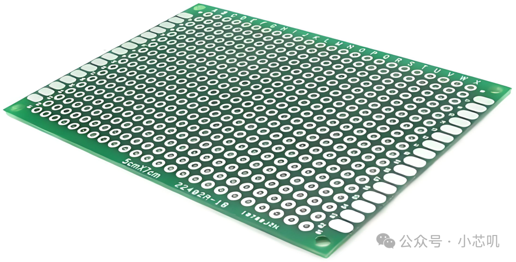
Perfboard is also known as a matrix board or universal board.
The most common color of perfboard is green, covered with a regular array of holes, each hole surrounded by an independent copper pad, with a pad spacing of 2.54mm, which is the industry standard spacing, compatible with the pin spacing of through-hole components. Unlike PCBs, perfboards do not have predefined circuit traces; we need to connect various components by soldering wires and jumpers.
After completing prototype validation, before officially producing PCBs, we usually use perfboards to solidify the circuits from the breadboard.The physical connections and electrical continuity after soldering on perfboards are more reliable, avoiding potential contact issues that may occur on breadboards, and allowing for testing the long-term stability of the circuit.
 3
3
PCB and PCBA
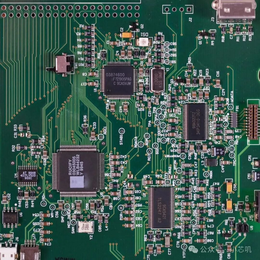
PCB stands for Printed Circuit Board. A PCB is a bare board that contains no electronic components, only copper traces, pads, and vias.
PCBA stands for Printed Circuit Board Assembly. The finished product after soldering all components such as resistors, capacitors, modules, and chips onto the PCB is called PCBA.
After validating with the perfboard, the next step is to convert the circuit on the perfboard into standardized design files.Common PCB design software includes Altium Designer and KiCad.Afterward, the designed PCB is exported as a Gerber file, along with a bill of materials, to be sent to the manufacturer for production.
From an idea to a customized product, breadboards, perfboards, and PCBs have clear roles at various stages of hardware design development. Breadboards are responsible for validating the feasibility of circuit logic; perfboards are used to solidify prototypes and test circuit stability; PCBs are for customized circuits, preparing for mass production; finally, all components are soldered onto the PCB to achieve productization.
Thank you for reading my article. If you found it helpful, please give me afollow. Let’s chat again next time.
>/ Author: Xiao Xin Ji