Click the blue text to follow us
0 Introduction
Welding is an essential construction technique in shipbuilding, and the quality of welds directly affects the structure, service life, and safety reliability of ships. Therefore, welds must undergo Non-Destructive Testing (NDT). Currently, conventional film Radiography Testing (RT) is widely used in the quality inspection of welds in shipbuilding, while Digital Radiography Testing (DRT) is less commonly applied. A significant reason for this is whether DRT technology has equivalent defect detection capabilities to conventional film RT technology, i.e., the equivalence issue, which concerns whether defects can be correctly displayed in terms of shape, size, and distribution on the detection images, and whether the nature and quality level of defects can be accurately judged. Research on equivalence issues in the field of shipbuilding is currently limited. In recent years, both domestic and international studies have primarily conducted numerous comparative tests of defect detection and image quality recognition, discussing the defect detection capabilities of the two technologies based on the fundamental theory of the imaging process, theoretically addressing the equivalence issue from the perspective of whether they constitute imaging systems with equivalent imaging quality.
X-ray DRT technology is classified into two levels: Level AB is medium sensitivity technology; Level B is high sensitivity technology. RT technology is classified into three levels: Level A is low sensitivity technology; Level AB is medium sensitivity technology; Level B is high sensitivity technology. This study focuses on steel materials with a thickness of 7.000 to 32.000 mm, using Level AB technology as an example for research.
1 Requirements for Equivalence of Detection Technology Standards
1.1 Sensitivity Indicators
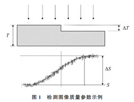
The basic principle of DRT and RT is to utilize the different thicknesses that X-rays penetrate, resulting in different radiation intensity received by the detector, thereby identifying defects through the unevenness of DRT and RT images. An important indicator of image quality for DRT and RT is contrast, usually defined as the ratio of the signal difference ΔS between two regions of the detection image to the signal S of the image, which is the ratio of the primary X-ray intensity difference ΔI caused by a small thickness difference ΔT to the X-ray intensity I. The quality parameters of the detection image are shown in Figure 1, where T is the thickness of the radiograph.
The contrast C of the detection image is

Where: μ is the linear attenuation coefficient of X-rays; n is the scattering ratio (the ratio of primary X-ray intensity to scattered X-ray intensity).
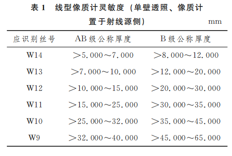
Typically, the contrast of DRT and RT images is assessed through a linear image quality meter. The requirements for the linear image quality meter are identical in “Non-Destructive Testing of Pressure Equipment”: Part 11: X-ray Digital Imaging Testing: NB/T 47013.11-2015 [S7.2015] and “Non-Destructive Testing of Pressure Equipment”: Part 2: Radiographic Testing: NB/T 47013.2-2015 [S].2015. The sensitivity of the linear image quality meter (single-wall radiography, with the meter placed on the radiation source side) is shown in Table 1.
1.2 Unclarity Indicators
The unclarity of DRT and RT is mainly divided into geometric unclarity and inherent unclarity. The RT technology standard only specifies the geometric unclarity indicators, while the inherent unclarity is controlled by restricting the maximum allowable radiographic energy. No specific indicators for total unclarity are provided; however, the DRT standard specifies the use of dual-line image quality meters to measure the spatial resolution of images based on nominal thickness, controlling the total unclarity of data images. According to the theoretical requirements of RT standards, the geometric unclarity U is derived, determining the spatial resolution and the line number value that RT should achieve with dual-line image quality meters.
The unclarity U is determined by geometric unclarity Dg and inherent unclarity Ui, with the relationship expressed as

Ug is determined by the distance from the radiation source to the workpiece and the thickness of the workpiece. The requirements for the distance from the radiation source to the workpiece are the same in “Non-Destructive Testing of Pressure Equipment”: Part 11: X-ray Digital Imaging Testing: NB/T 47013.11-2015 [S7.2015] and “Non-Destructive Testing of Pressure Equipment”: Part 2: Radiographic Testing: NB/T 47013.2-2015 [S].2015, with the formula being

Where: f is the distance from the radiation source to the surface of the workpiece; d is the focal size; b is the distance from the surface of the workpiece to the detector.
It can be concluded that Ug is

For RT technology, the inherent unclarity Ui film of conventional film is generated by the scattering of electrons excited in the emulsion layer of the conventional film by the radiation. The size of Ui film is the average distance of the scattered electrons acting in the emulsion layer of the conventional film, which mainly depends on the energy of the radiation. When the X-ray tube voltage is 100~400 kV, the empirical formula for expressing Ui film of conventional film is

Where: V is the tube voltage in kV.
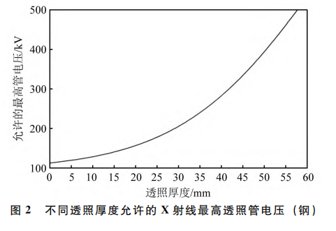
In RT technology, the maximum allowable X-ray tube voltage (steel) for different radiographic thicknesses is shown in Figure 2.
In summary, when studying the equivalence of unclarity indicators between DRT and RT, both Ug are the same, and it is only necessary to calculate the inherent unclarity Ui film of the conventional film based on the maximum allowable radiographic energy, while the inherent unclarity Ui digital of DRT is limited by the pixel size of the detector and can be simply calculated using formula (6). Ultimately, the equivalence of the corresponding detection standards of DRT and RT is discussed based on the calculation results of formula (2).

Where: P is the effective pixel size of the detector.
1.3 Normalized Signal-to-Noise Ratio SNRn
In “Non-Destructive Testing of Pressure Equipment: Part 2: Radiographic Testing: NB/T 47013.2-2015 [S].2015”, conventional film RT technology defines the “signal-to-noise ratio” as the ratio of film blackness to granularity at that blackness, which is positively correlated with the ratio of gradient to noise. The signal-to-noise ratio can be calculated based on gradient data as follows:

Where: G2 is the gradient at blackness D=2.0; σD is the granularity of the X-ray film, with specified values shown in Table 2.
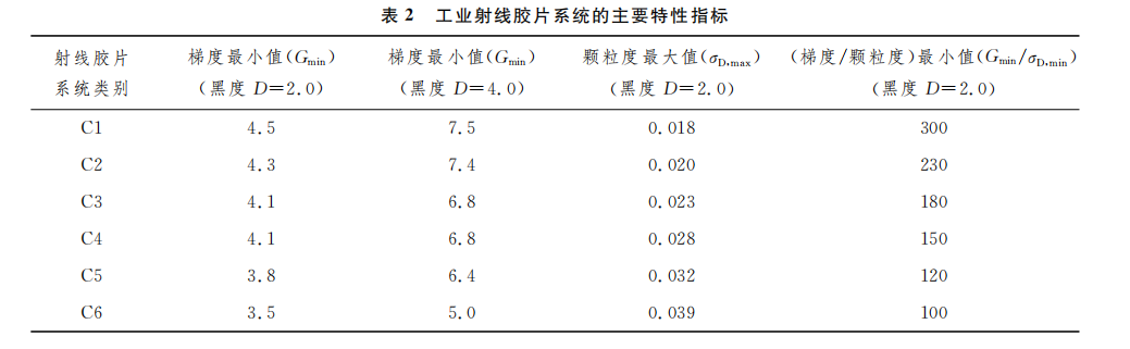
According to the requirements of “Non-Destructive Testing of Pressure Equipment: Part 2: Radiographic Testing: NB/T 47013.2-2015 [S].2015”, AB level technology should use C5 or higher category X-ray film (C1 being the highest category), and blackness D should be no less than 2.0. The normalized signal-to-noise ratio SNRn of AB level technology in conventional film RT should be greater than 62.50 (2.0/0.032).
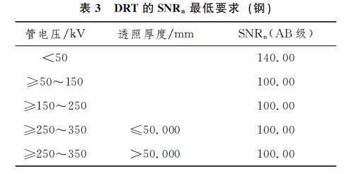
The minimum requirements for the SNRn of DRT for steel materials are specified in “Non-Destructive Testing of Pressure Equipment: Part 11: X-ray Digital Imaging Testing: NB/T 47013.11-2015 [S].2015”, as shown in Table 3.
1.4 Assessment of Equivalence of Detection Technology Standards
Summarizing the AB level technology data from “Non-Destructive Testing of Pressure Equipment: Part 11: X-ray Digital Imaging Testing: NB/T 47013.11-2015 [S].2015” and “Non-Destructive Testing of Pressure Equipment: Part 2: Radiographic Testing: NB/T 47013.2-2015 [S].2015”, as shown in Table 4.
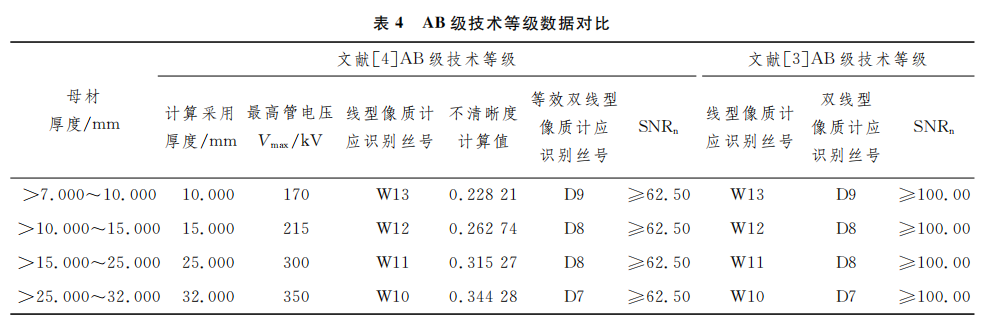
From Table 4, it can be seen that regarding the three aspects of quality indicators of the detection images, the requirements specified in “Non-Destructive Testing of Pressure Equipment: Part 11: X-ray Digital Imaging Testing: NB/T 47013.11-2015 [S].2015” all meet the requirements of “Non-Destructive Testing of Pressure Equipment: Part 2: Radiographic Testing: NB/T 47013.2-2015 [S].2015”, indicating that the AB level technology requirements of DRT meet the AB level technology requirements of conventional film RT.
2 Detection Equivalence Test
2.1 Test Parameters
The test parameters for conventional film RT and DRT are as follows:
(1) Conventional film RT test parameters: AGFA C7; radiation source focal size 1.000 mm; focal distance: 800.000 mm; exposure time: 3s; tube current: 5mA; three different thickness test plates tube voltage: 250 kV (18.000 mm), 260 kV (20.000 mm), 265 kV (22.000 mm).
(2) DRT test parameters
Detector pixel size: 100.00 μm; radiation source focal size: 1.000 mm; exposure time: 3 s; tube current: 3 mA; average number of times: 5; three different thickness test plates tube voltage: 175 kV (18.000 mm), 190 kV (20.000 mm), 200 kV (22.000 mm).
2.2 Test Results
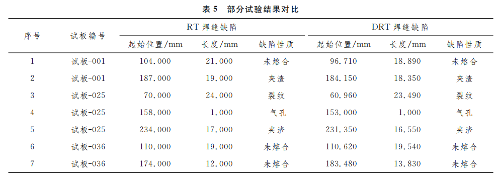
The equivalence test plates were processed and produced by a professional NDT test plate processing factory, totaling 36 pieces, with the ultrasonic testing (UT) factory report showing a total of 99 artificial defects, including 32 slag inclusions, 9 pores, 24 cracks, and 34 lack of fusion. Some test results are compared in Table 5.
In the conventional film RT test results, the minimum blackness was 2.1, and the sensitivity of the linear image quality meter was W12, meeting the AB level technology requirements specified in “Non-Destructive Testing of Pressure Equipment: Part 2: Radiographic Testing: NB/T 47013.2-2015 [S].2015”.
In the DRT test results, the minimum SNRn was 124.32; the minimum sensitivity of the dual-line image quality meter was D9; the minimum sensitivity of the linear image quality meter was W13, meeting the AB level technology requirements specified in “Non-Destructive Testing of Pressure Equipment: Part 11: X-ray Digital Imaging Testing: NB/T 47013.11-2015 [S].2015”.
2.3 Comparative Analysis of Test Data
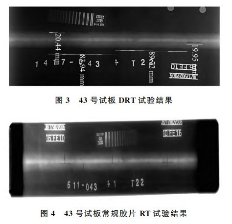
In comparison to the factory UT report for the test plates, the DRT results did not detect 2 lack of fusion defects, while the conventional film RT results did not detect 1 lack of fusion defect. Taking the lack of fusion defect on test plate 43 as an example, it was detected by RT but not by DRT, as shown in Figures 3 and 4. Lack of fusion defects are area-type defects, and due to the significant influence of the radiographic angle, the detection rate of RT for lack of fusion type defects is relatively lower compared to UT. All other types of test plate defects were detectable by DRT. Compared to the results of conventional film RT, the average difference in defect measurement length for DRT results was 2.600 mm, with the nature of the defects being judged the same.
3 Conclusion
(1) Through comparison of contrast indicators, unclarity indicators, and SNR, the AB level technology requirements specified in “Non-Destructive Testing of Pressure Equipment: Part 11: X-ray Digital Imaging Testing: NB/T 47013.11-2015 [S].2015” all meet the AB level technology requirements specified in “Non-Destructive Testing of Pressure Equipment: Part 2: Radiographic Testing: NB/T 47013.2-2015 [S].2015”, indicating that for steel materials with flat butt welds and a thickness of 7.000 to 32.000 mm, the AB level technology in “Non-Destructive Testing of Pressure Equipment: Part 11: X-ray Digital Imaging Testing: NB/T 47013.11-2015 [S].2015” has the same defect detection capability as the AB level technology in “Non-Destructive Testing of Pressure Equipment: Part 2: Radiographic Testing: NB/T 47013.2-2015 [S].2015”.
(2) By implementing DRT according to the AB level technology requirements specified in “Non-Destructive Testing of Pressure Equipment: Part 11: X-ray Digital Imaging Testing: NB/T 47013.11-2015 [S].2015” and implementing conventional film RT according to the AB level technology requirements specified in “Non-Destructive Testing of Pressure Equipment: Part 2: Radiographic Testing: NB/T 47013.2-2015 [S].2015”, the experimental verification confirms that both have the same defect detection capability.
Source: “Shipbuilding Technology”, Volume 51, Issue 6, December 2023
Liu Siming, Lu Zhipeng, Huang Kaihua, Zhou Changzhi, Yin Jiawen
(Shanghai Shipbuilding Technology Research Institute, Shanghai 200032)

·END·