1. What is a Hardware Driver Module
In embedded systems, a hardware driver module acts like a bridge, connecting hardware devices on one end and upper-level software on the other, playing a crucial role in the entire system. In simple terms, a hardware driver module is a piece of program code specifically responsible for interacting with hardware devices, enabling control and management of these devices.
Various electronic devices we use daily, such as smartphones, smartwatches, and industrial controllers, contain a wide variety of internal hardware, including processors, sensors, displays, and communication modules. Each type of hardware has its unique operating methods and control mechanisms. Without hardware driver modules, it would be nearly impossible for upper-level software to directly control these hardware components.
For example, in a smartwatch, the hardware driver module is responsible for communicating with the accelerometer, reading the acceleration data it detects, and converting this data into a format that upper-level software can understand. The health monitoring software calls the interfaces provided by the driver to obtain acceleration data, which is then used to analyze the user’s step count, exercise intensity, and other information. Without the corresponding hardware driver module, the data detected by the sensor cannot be read and processed correctly, and the motion monitoring function of the smartwatch would not be achievable.
2. Why Use C Language to Develop Hardware Driver Modules
2.1. Efficient Hardware Operation Capability
The C language possesses efficient hardware operation capabilities, allowing developers to directly manipulate hardware registers and memory. For instance, in GPIO (General Purpose Input/Output) driver development, we often need to control the pin level states to manage external devices, such as turning an LED on or off or reading the state of a button. In C, we can define a pointer to the GPIO register and directly read and write to the register, thus accurately controlling the pin level. Assuming the GPIO port register address is 0x40010800, we can define a pointer to that register: volatile unsigned int *GPIO_REG = (volatile unsigned int *)0x40010800;. The volatile keyword is crucial as it tells the compiler not to optimize this variable, since the value of the hardware register may change at any time due to external hardware. We can then use this pointer to control the pin level, for example, setting the pin to high: *GPIO_REG |= (1 << pin_number;, where pin_number indicates the pin number to control. This direct manipulation of registers avoids the overhead of complex function calls and intermediate layers, resulting in extremely high code execution efficiency and rapid response to hardware demands.
2.2. Good Portability
The C language has good portability; hardware driver modules developed in C can be reused across different hardware platforms, reducing development costs and workload. Regardless of the hardware platform, as long as the C language standard is followed, the behavior of these functions and data types remains consistent. Additionally, the syntax of C is concise and flexible, not dependent on specific hardware platforms or operating systems, facilitating cross-platform code portability.
For example, when developing a UART (Universal Asynchronous Receiver-Transmitter) driver, different models of microcontrollers may have differences in hardware register addresses and configuration methods. However, we can use C’s conditional compilation directives (such as #ifdef, #endif) and macro definitions to configure and initialize the UART module based on different hardware platforms. For instance, with STM32 and MSP430, two common microcontrollers, although their UART register addresses and configuration methods differ, we can write the following C code framework to achieve similar UART driver functionality:
#ifdef STM32
// UART initialization code for STM32
void uart_init() {
    // Configure STM32's UART registers, such as setting baud rate, data bits, stop bits, etc.
    // Assuming using USART1
    RCC_APB2PeriphClockCmd(RCC_APB2Periph_USART1, ENABLE);
    USART_InitTypeDef USART_InitStructure;
    USART_InitStructure.USART_BaudRate = 9600;
    USART_InitStructure.USART_WordLength = USART_WordLength_8b;
    USART_InitStructure.USART_StopBits = USART_StopBits_1;
    USART_InitStructure.USART_Parity = USART_Parity_No;
    USART_InitStructure.USART_HardwareFlowControl = USART_HardwareFlowControl_None;
    USART_InitStructure.USART_Mode = USART_Mode_Rx | USART_Mode_Tx;
    USART_Init(USART1, &USART_InitStructure);
    USART_Cmd(USART1, ENABLE);
}
#elif defined(MSP430)
// UART initialization code for MSP430
void uart_init() {
    // Configure MSP430's UART registers, such as setting baud rate, data bits, stop bits, etc.
    // Assuming using UCA0
    UCA0CTL1 |= UCSWRST;
    UCA0CTL1 |= UCSSEL_2; // Select SMCLK
    UCA0BR0 = 104; // 1MHz 9600
    UCA0BR1 = 0;
    UCA0MCTL = UCBRS_1;
    UCA0CTL1 &= ~UCSWRST;
    UCA0IE |= UCRXIE; // Enable receive interrupt
}
#endif
In the above code, by using #ifdef and #elif defined directives, we can write corresponding UART initialization code based on different hardware platforms (STM32 or MSP430). Thus, on different hardware platforms, we only need to modify the conditional compilation directives and the corresponding hardware-related code to reuse most of the driver logic, enhancing code portability.
3. Hardware Driver Module Development Process
3.1. Requirements and Hardware Manual
Developers need to thoroughly read the hardware manual and datasheet to understand the hardware’s functions, register configurations, interface specifications, and other key information. Understanding the internal architecture of the hardware, including its various sub-modules, registers, and interrupt mechanisms, is essential. It is also necessary to determine what specific functions the driver module needs to implement and which hardware devices it needs to support.
Next, it is important to study the hardware manual. Understanding hardware interfaces, register definitions, electrical characteristics, etc., is crucial. For example, in developing a driver for an SPI interface Flash memory, the hardware manual provides information on the pin definitions for the SPI interface, such as MOSI (Master Out Slave In), MISO (Master In Slave Out), SCK (Serial Clock), and CS (Chip Select), and which pins they connect to on the microcontroller. Additionally, detailed information about registers can be obtained, such as the status register indicating the Flash’s operational status and the command register for receiving various operation commands (like read data, write data, erase operations, etc.). Only by deeply understanding the hardware operation information can one configure and control the hardware effectively.
3.2. Writing Driver Code
1. Writing Initialization Functions
The purpose of the initialization function is to perform initial configuration of the hardware device, putting it into a working state. Taking the SPI driver initialization as an example, here is a piece of C code based on STM32:
#include "stm32f10x.h"
void SPI_InitFunction(void) {
    SPI_InitTypeDef SPI_InitStructure;
    GPIO_InitTypeDef GPIO_InitStructure;
    // Enable SPI and GPIO clocks
    RCC_APB2PeriphClockCmd(RCC_APB2Periph_SPI1 | RCC_APB2Periph_GPIOA, ENABLE);
    // Configure SPI GPIO pins
    GPIO_InitStructure.GPIO_Pin = GPIO_Pin_5 | GPIO_Pin_6 | GPIO_Pin_7;
    GPIO_InitStructure.GPIO_Speed = GPIO_Speed_50MHz;
    GPIO_InitStructure.GPIO_Mode = GPIO_Mode_AF_PP;
    GPIO_Init(GPIOA, &GPIO_InitStructure);
    // Configure SPI parameters
    SPI_InitStructure.SPI_Direction = SPI_Direction_2Lines_FullDuplex;
    SPI_InitStructure.SPI_Mode = SPI_Mode_Master;
    SPI_InitStructure.SPI_DataSize = SPI_DataSize_8b;
    SPI_InitStructure.SPI_CPOL = SPI_CPOL_Low;
    SPI_InitStructure.SPI_CPHA = SPI_CPHA_1Edge;
    SPI_InitStructure.SPI_NSS = SPI_NSS_Soft;
    SPI_InitStructure.SPI_BaudRatePrescaler = SPI_BaudRatePrescaler_16;
    SPI_InitStructure.SPI_FirstBit = SPI_FirstBit_MSB;
    SPI_InitStructure.SPI_CRCCalculation = SPI_CRCCalculation_Disable;
    SPI_Init(SPI1, &SPI_InitStructure);
    // Enable SPI
    SPI_Cmd(SPI1, ENABLE);
}
In this code, the clocks for SPI1 and GPIOA are first enabled, then the GPIO pins for SPI1 (PA5, PA6, PA7) are configured to work in alternate push-pull output mode. Next, the working mode, data size, clock polarity, clock phase, baud rate prescaler, and other parameters for SPI1 are set, and finally, SPI1 is enabled. With this initialization configuration, the SPI interface can operate normally, preparing for data transmission between the master and slave devices.
Building the file_operations Structure: In Linux driver development, the file_operations structure is the core part of character device drivers, defining a series of function pointers for various operations on the character device. When a user program operates on the device file (such as opening, reading, writing, etc.), the kernel calls the corresponding operation function based on the file structure’s file_operations pointer.
For a simple character device driver, suppose we are developing a character device driver to control an LED. Below is an example code for constructing the file_operations structure:
#include <linux/module.h>
#include <linux/kernel.h>
#include <linux/fs.h>
#include <linux/init.h>
#include <linux/cdev.h>
#include <asm/uaccess.h>
#define LED_MAJOR 250
#define LED_MINOR 0
#define LED_DEV_NAME "led_dev"
static dev_t devno;
static struct cdev led_cdev;
static struct class *led_class;
static struct device *led_device;
// Open device function
static int led_open(struct inode *inode, struct file *filp) {
    // Initialize LED related operations, such as setting GPIO to output mode, etc.
    printk(KERN_INFO "LED device opened.\n");
    return 0;
}
// Read device function
static ssize_t led_read(struct file *filp, char __user *buf, size_t count, loff_t *offt) {
    // Read data from LED device, here simply return 0
    return 0;
}
// Write device function
static ssize_t led_write(struct file *filp, const char __user *buf, size_t count, loff_t *offt) {
    char user_buf[10];
    if (copy_from_user(user_buf, buf, count)) {
        return -EFAULT;
    }
    // Control LED based on written data, such as turning on or off
    if (user_buf[0] == '1') {
        // Turn on LED operation
        printk(KERN_INFO "LED turned on.\n");
    } else if (user_buf[0] == '0') {
        // Turn off LED operation
        printk(KERN_INFO "LED turned off.\n");
    }
    return count;
}
// Release device function
static int led_release(struct inode *inode, struct file *filp) {
    printk(KERN_INFO "LED device released.\n");
    return 0;
}
// Instantiate file_operations structure
static const struct file_operations led_fops = {
   .owner = THIS_MODULE,
   .open = led_open,
   .read = led_read,
   .write = led_write,
   .release = led_release,
};
In the above code, functions led_open, led_read, led_write, and led_release are defined to implement the device’s open, read, write, and release operations, respectively. These function pointers are then assigned to the file_operations structure led_fops. During driver initialization, this structure is registered with the kernel, allowing user programs to perform corresponding operations on the LED device through the device file.
2. Writing Interrupt Handler Functions
Below is an example of writing a key interrupt handler function, assuming we are using an STM32 microcontroller with the key connected to pin PA0:
#include "stm32f10x.h"
void EXTI0_IRQHandler(void) {
    if (EXTI_GetITStatus(EXTI_Line0)!= RESET) {
        // Handle key press operation, such as reading key state, executing corresponding functions, etc.
        if (GPIO_ReadInputDataBit(GPIOA, GPIO_Pin_0) == 0) {
            // Key pressed
            // Add handling code for key press here, such as controlling LED blinking, sending data, etc.
            printk(KERN_INFO "Button pressed.\n");
        }
        // Clear interrupt flag
        EXTI_ClearITPendingBit(EXTI_Line0);
    }
}
In this code, we first check if an interrupt has occurred on EXTI_Line0 (corresponding to the PA0 interrupt line). If an interrupt has occurred, we read the input data from the PA0 pin to determine if the key has been pressed. If the key is pressed, we can add specific handling logic in the corresponding code block. Finally, we clear the interrupt flag to ensure that the interrupt can be correctly responded to next time.
3.3. Testing and Debugging
After completing the driver code, it is necessary to test and debug the driver on actual hardware to ensure it operates correctly. An oscilloscope can be used to monitor hardware signals; for example, in SPI driver testing, we can observe the SPI clock signal (SCK) and data signals (MOSI, MISO) with the oscilloscope to check if the signal waveforms are normal and comply with the SPI communication protocol specifications.
During debugging, serial output of debug information is a common method. By adding print statements in the driver code, we can output the values of key variables, the execution status of functions, and other information through the serial port to facilitate observation and analysis of the program’s operation. For example, in the above LED driver’s write function, we can add printk(KERN_INFO "Received data: %c\n", user_buf[0]); statement, so that when data is written to the LED device, we can see the received data through the serial port. Using a JTAG/SWD debugger for step-by-step debugging is also a very effective method. The debugger can connect to the target board and communicate with the debugging interface (such as JTAG or SWD) on the target board, allowing for step execution, setting breakpoints, and viewing register and memory contents. During step debugging, we can execute the driver code line by line and observe the results of each step to locate and resolve issues.
4. Case Study: Driving an OLED Display
4.1. Hardware Connection
Using a common 0.96-inch SPI interface OLED display connected to an STM32 development board. The OLED display communicates with the STM32 via the SPI bus. The specific wiring method is as follows:
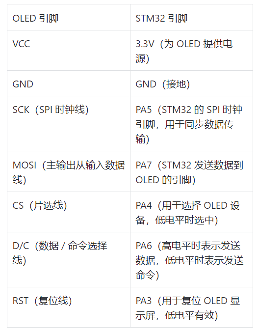
4.2. Writing Driver Code
1. Initializing GPIO Ports
The control pins of the OLED display need to be configured as output mode so that the STM32 can send signals to it. For example, to configure PA3, PA4, PA5, PA6, and PA7, the code is as follows:
#include "stm32f10x.h"
void GPIO_Init(void){
    GPIO_InitTypeDef GPIO_InitStructure;
    // Enable GPIOA clock
    RCC_APB2PeriphClockCmd(RCC_APB2Periph_GPIOA, ENABLE);
    // Configure PA3 as push-pull output mode for OLED reset
    GPIO_InitStructure.GPIO_Pin = GPIO_Pin_3;
    GPIO_InitStructure.GPIO_Speed = GPIO_Speed_50MHz;
    GPIO_InitStructure.GPIO_Mode = GPIO_Mode_Out_PP;
    GPIO_Init(GPIOA, &GPIO_InitStructure);
    // Configure PA4 as push-pull output mode for OLED chip select
    GPIO_InitStructure.GPIO_Pin = GPIO_Pin_4;
    GPIO_Init(GPIOA, &GPIO_InitStructure);
    // Configure PA5 as alternate push-pull output mode for SPI clock
    GPIO_InitStructure.GPIO_Pin = GPIO_Pin_5;
    GPIO_InitStructure.GPIO_Mode = GPIO_Mode_AF_PP;
    GPIO_Init(GPIOA, &GPIO_InitStructure);
    // Configure PA6 as push-pull output mode for data/command selection
    GPIO_InitStructure.GPIO_Pin = GPIO_Pin_6;
    GPIO_Init(GPIOA, &GPIO_InitStructure);
    // Configure PA7 as alternate push-pull output mode for SPI data output
    GPIO_InitStructure.GPIO_Pin = GPIO_Pin_7;
    GPIO_InitStructure.GPIO_Mode = GPIO_Mode_AF_PP;
    GPIO_Init(GPIOA, &GPIO_InitStructure);
}
2. SPI Initialization
The SPI communication protocol is used for OLED control, which synchronizes data transmission through the clock line (SCK). The master (STM32) sends data to the slave (OLED) via the master output slave input line (MOSI), while the slave sends data back to the master via the master input slave output line (MISO) (in this OLED control, MISO is not used). The initialization parameter settings are as follows:
void SPI_Init(void){
    SPI_InitTypeDef SPI_InitStructure;
    // Enable SPI1 clock
    RCC_APB2PeriphClockCmd(RCC_APB2Periph_SPI1, ENABLE);
    // Configure SPI1 as master mode, clock rate fPCLK2/8
    SPI_InitStructure.SPI_Direction = SPI_Direction_2Lines_FullDuplex;
    SPI_InitStructure.SPI_Mode = SPI_Mode_Master;
    SPI_InitStructure.SPI_DataSize = SPI_DataSize_8b;
    SPI_InitStructure.SPI_CPOL = SPI_CPOL_Low;
    SPI_InitStructure.SPI_CPHA = SPI_CPHA_1Edge;
    SPI_InitStructure.SPI_NSS = SPI_NSS_Soft;
    SPI_InitStructure.SPI_BaudRatePrescaler = SPI_BaudRatePrescaler_8;
    SPI_InitStructure.SPI_FirstBit = SPI_FirstBit_MSB;
    SPI_InitStructure.SPI_CRCPolynomial = 7;
    SPI_Init(SPI1, &SPI_InitStructure);
    // Enable SPI1
    SPI_Cmd(SPI1, ENABLE);
}
Sending Commands and Data to the OLED: Functions need to be written to send commands and data to the OLED according to its communication protocol. When sending commands, the D/C pin is set low; when sending data, the D/C pin is set high. The code is as follows:
// Send a byte of data to SPI1
void SPI_SendByte(uint8_t Byte){
    while (SPI_I2S_GetFlagStatus(SPI1, SPI_I2S_FLAG_TXE) == RESET);
    SPI_I2S_SendData(SPI1, Byte);
}
// Send OLED command
void OLED_WriteCmd(uint8_t Cmd){
    GPIO_ResetBits(GPIOA, GPIO_Pin_6);  // D/C = 0, send command
    GPIO_ResetBits(GPIOA, GPIO_Pin_4);  // CS = 0, select OLED
    SPI_SendByte(Cmd);
    GPIO_SetBits(GPIOA, GPIO_Pin_4);    // CS = 1, deselect
}
// Send OLED data
void OLED_WriteData(uint8_t Data){
    GPIO_SetBits(GPIOA, GPIO_Pin_6);  // D/C = 1, send data
    GPIO_ResetBits(GPIOA, GPIO_Pin_4);  // CS = 0, select OLED
    SPI_SendByte(Data);
    GPIO_SetBits(GPIOA, GPIO_Pin_4);    // CS = 1, deselect
}
OLED Initialization Function: Initializing the OLED display requires sending a series of initialization commands according to the OLED’s datasheet. The common initialization process and key commands are as follows:
void OLED_Init(void){
    // Hardware reset OLED
    GPIO_ResetBits(GPIOA, GPIO_Pin_3);
    delay_ms(100);
    GPIO_SetBits(GPIOA, GPIO_Pin_3);
    delay_ms(100);
    // Send initialization commands
    OLED_WriteCmd(0xAE);  // Display off
    OLED_WriteCmd(0xD5);  // Set display clock division ratio/oscillator frequency
    OLED_WriteCmd(0x80);
    OLED_WriteCmd(0xA8);  // Set multiplex ratio
    OLED_WriteCmd(0x3F);
    OLED_WriteCmd(0xD3);  // Set display offset
    OLED_WriteCmd(0x00);
    OLED_WriteCmd(0x40);  // Set display start line
    OLED_WriteCmd(0xA1);  // Set segment remap
    OLED_WriteCmd(0xC8);  // Set COM output scan direction
    OLED_WriteCmd(0xDA);  // Set COM pin hardware configuration
    OLED_WriteCmd(0x12);
    OLED_WriteCmd(0x81);  // Set contrast control register
    OLED_WriteCmd(0xCF);
    OLED_WriteCmd(0xD9);  // Set pre-charge period
    OLED_WriteCmd(0xF1);
    OLED_WriteCmd(0xDB);  // Set VCOMH
    OLED_WriteCmd(0x30);
    OLED_WriteCmd(0xA4);  // Set output follow RAM content
    OLED_WriteCmd(0xA6);  // Set normal display
    OLED_WriteCmd(0x8D);  // Set charge pump enable
    OLED_WriteCmd(0x14);
    OLED_WriteCmd(0xAF);  // Display on
}
3. Writing Display Functions
To display characters, the character’s font data must be obtained first, and then the font data is sent byte by byte to the OLED’s display memory. Assuming we have a character font array Font8x16, the function to display a character is as follows:
void OLED_ShowChar(uint8_t x, uint8_t y, char ch){
    uint8_t i, j;
    ch -= 32;  // Character ASCII code offset
    for (i = 0; i < 8; i++)
    {
        OLED_SetCursor(x, y);
        for (j = 0; j < 8; j++)
        {
            OLED_WriteData(Font8x16[ch * 16 + i] & (1 << (7 - j))? 0xFF : 0x00);
        }
        y++;
    }
}
When displaying a string, we can simply call the character display function sequentially:
void OLED_ShowString(uint8_t x, uint8_t y, char *str){
    while (*str)
    {
        OLED_ShowChar(x, y, *str);
        x += 8;
        if (x > 120)
        {
            x = 0;
            y += 16;
        }
        str++;
    }
}
Displaying images requires sending the pixel data of the image byte by byte to the OLED’s display memory. Assuming we have an image data array image, the function to display an image is as follows:
void OLED_ShowImage(uint8_t x, uint8_t y, uint8_t *image){
    uint8_t i, j;
    for (i = 0; i < 8; i++)
    {
        OLED_SetCursor(x, y + i);
        for (j = 0; j < 128; j++)
        {
            OLED_WriteData(image[i * 128 + j]);
        }
    }
}
Here, the OLED_SetCursor function is used to set the cursor position of the OLED, and the code is as follows:
void OLED_SetCursor(uint8_t x, uint8_t y){
    OLED_WriteCmd(0xB0 + y);
    OLED_WriteCmd((x & 0xF0) >> 4 | 0x10);
    OLED_WriteCmd(x & 0x0F);
}
4.3. Debugging and Optimization
1. Common Issues
(1) OLED Not Displaying
Reason: Hardware connection errors are one of the common causes, which may be due to loose or incorrect connections of the OLED’s power line, data line, control line, etc., with the STM32 development board; it may also be due to OLED initialization failures, such as incorrect command sending or timing issues; additionally, insufficient power supply may also cause the OLED to not function properly. The operating voltage for OLED is generally 3.3V, and if the supply voltage is unstable or below the normal operating voltage, it will result in no display.
Solution: Carefully check the hardware connections against the wiring diagram, ensuring each wire is connected correctly and securely. A multimeter can be used to measure the continuity of the connection lines; recheck the OLED initialization code to ensure that the initialization commands are sent correctly according to the OLED datasheet, paying attention to the order and parameter settings. Debug information can also be added to the initialization code to print out during the process to check if it is functioning normally; check the power supply circuit to ensure the 3.3V power is stable, and consider using a power module to supply power to the OLED separately or adding filter capacitors to the power line to reduce power fluctuations.
(2) Displaying Garbage Characters
Reason: Data transmission errors may lead to garbage characters being displayed, such as when the data transmission rate during SPI communication exceeds the OLED’s processing capability, or if the clock polarity and clock phase settings for SPI communication are incorrect, leading to data sampling errors. Additionally, errors in font data can also cause garbage characters to appear if the font library used does not match the OLED’s display method, or if errors occur during the storage or retrieval of font data.
Solution: Adjust the SPI communication clock rate to appropriately lower the data transmission speed, ensuring the OLED can correctly receive and process data. Also, check the clock polarity (CPOL) and clock phase (CPHA) settings for SPI communication to ensure they match the OLED’s requirements. Verify the font data to confirm the correctness of the font library and whether the reading and transmission processes for the font data are correct. This can be done by printing the font data in the code or comparing it with the correct font table to find errors.
(3) Screen Flickering
Reason: Insufficient refresh rate is the main cause of screen flickering. If the OLED’s refresh frequency is too low, the human eye will perceive the flickering. Additionally, hardware interference may also cause screen flickering, such as surrounding electromagnetic interference or power ripple affecting the OLED’s normal operation.
Solution: Optimize the display code to increase the OLED’s refresh frequency, such as reducing unnecessary display operations and properly scheduling display tasks to ensure timely completion of frame updates. Strengthen hardware anti-interference measures by adding filter capacitors to the OLED’s power line to reduce power ripple; arrange shielding layers around the OLED to reduce electromagnetic interference, and consider shielding the SPI communication lines to improve data transmission stability.
2. Performance Optimization
(1) Optimizing SPI Communication Speed
Adjusting the clock prescaler: Understand the maximum SPI clock frequency supported by the OLED according to its datasheet, and then reasonably set the SPI clock prescaler in the STM32’s SPI initialization code to increase the SPI communication speed. For example, if the maximum clock frequency supported by the OLED is 18MHz, and the STM32’s APB bus clock is 72MHz, the SPI clock prescaler can be set to 4 to achieve an SPI clock frequency of 18MHz.
Using DMA for transmission: DMA (Direct Memory Access) can achieve fast data transmission without occupying CPU resources. Using DMA in SPI communication can greatly improve data transmission efficiency and reduce CPU wait times. For example, to send data, configure DMA to transfer the data from memory directly to the SPI data register, allowing the CPU to perform other tasks while DMA transfers data. The specific configuration steps are as follows:
Enable DMA clock, for example, for SPI1 using DMA1 channel 4, enable DMA1 clock with RCC_AHBPeriphClockCmd(RCC_AHBPeriph_DMA1, ENABLE);.
Configure the DMA channel, including setting the transfer direction (memory to peripheral), data width (8-bit or 16-bit, according to SPI configuration), transfer mode (single transfer or circular transfer, etc.), priority, etc. For STM32F103, the code to configure DMA1 channel 4 for sending data via SPI1 is as follows:
DMA_InitTypeDef DMA_InitStructure;
DMA_InitStructure.DMA_PeripheralBaseAddr = SPI1_DR;  // SPI data register address
DMA_InitStructure.DMA_MemoryBaseAddr = (u32)send_buffer;  // Address of the data buffer to send
DMA_InitStructure.DMA_DIR = DMA_DIR_PeripheralDST;  // Transfer direction: memory to peripheral
DMA_InitStructure.DMA_BufferSize = buffer_size;  // Amount of data to transfer
DMA_InitStructure.DMA_PeripheralInc = DMA_PeripheralInc_Disable;  // Peripheral address does not increment
DMA_InitStructure.DMA_MemoryInc = DMA_MemoryInc_Enable;  // Memory address increments
DMA_InitStructure.DMA_PeripheralDataSize = DMA_PeripheralDataSize_Byte;  // Peripheral data width is byte
DMA_InitStructure.DMA_MemoryDataSize = DMA_MemoryDataSize_Byte;  // Memory data width is byte
DMA_InitStructure.DMA_Mode = DMA_Mode_Normal;  // Transfer mode: normal mode
DMA_InitStructure.DMA_Priority = DMA_Priority_High;  // Priority: high
DMA_InitStructure.DMA_M2M = DMA_M2M_Disable;  // Not memory to memory mode
DMA_Init(DMA1_Channel4, &DMA_InitStructure);  // Initialize DMA1 channel 4
Enable the DMA channel with DMA_Cmd(DMA1_Channel4, ENABLE);, and then start DMA transfer when sending data via SPI.
Reducing memory usage, optimizing data structures: When defining variables and data structures, use appropriate data types to avoid wasting memory with overly large data types. For example, if only integers between 0 and 255 need to be stored, use uint8_t type instead of int type; for flags, bit-fields can be used to define them to save memory. For instance, defining a structure containing multiple flags:
struct {
    unsigned int flag1 : 1;  // Occupies 1 bit space
    unsigned int flag2 : 1;  // Occupies 1 bit space
    unsigned int counter : 7;  // Occupies 7 bits space
} status;
Reasonably allocate memory: Avoid frequent dynamic memory allocation and deallocation during program execution, as dynamic memory allocation functions (like malloc and free) incur additional overhead and may lead to memory fragmentation. If larger memory space is needed, allocate it once at the start of the program and reuse it throughout the program’s execution; for local variables, allocate on the stack rather than the heap, as stack allocation and deallocation are faster.
Optimize code structure: Carefully review the code, removing any unused or duplicate code segments. This not only reduces code size but also improves code readability and maintainability. For example, if the same functional function is defined in multiple places with identical implementations, it can be merged into a single function.
Reduce function call overhead: For simple functions that are frequently called in the code, consider defining them as inline functions (using the inline keyword), so that during compilation, the function body code is directly inserted at the call site, avoiding the overhead of function calls and improving code execution efficiency. However, it should be noted that inline functions will increase code size, so they are not recommended for complex functions.