Many boys enjoy playing with toy guns, such as rubber band guns, water guns, and soft bullet guns. Engaging in shooting activities under safe conditions is a beneficial sport. Shooting is a skill that requires training to improve accuracy. Therefore, a target is needed as a training aid. There are various target products available on the market, and some people even make simple ones themselves or use existing items. As a small maker, have you considered using maker equipment and technology to create one? This article will introduce a method for making an electronic scoring target.
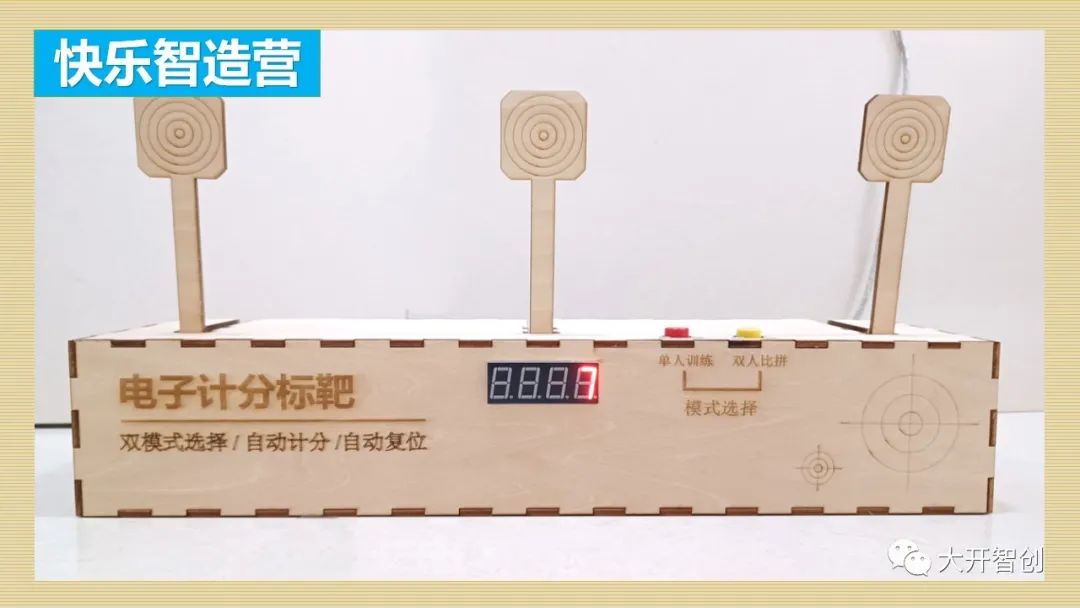
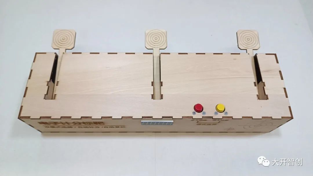
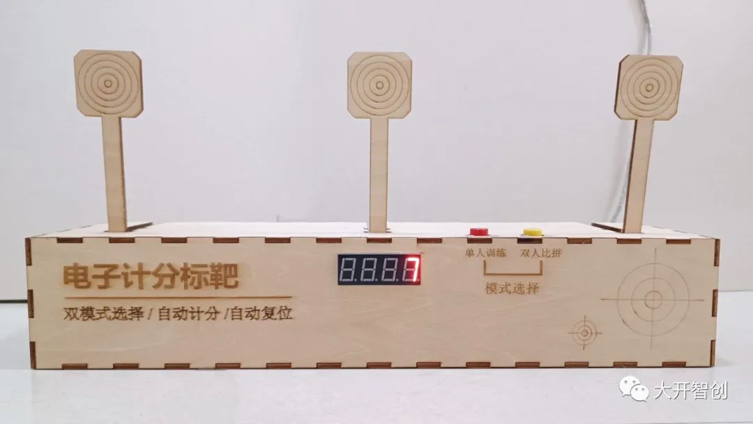
This machine has three targets and is designed with two operating modes, which can be set by pressing the corresponding buttons. The first is a single-player training mode, where the score accumulates and displays when any target is hit. The second is a two-player competition mode, where the leftmost and rightmost targets are assigned to two players, and hitting the middle target is invalid; each player’s score is displayed on the left and right sides of the screen respectively.
In both modes, when a target is hit, it falls backward and then automatically resets. Most similar products on the market require all three targets to fall before resetting simultaneously, but in this design, each target can reset individually. Of course, by modifying the program, we can achieve more functions and meet different needs.
The following video is from Dakaizhichuang
Demonstration Video↑
How are the automatic scoring and automatic resetting functions implemented in this project?
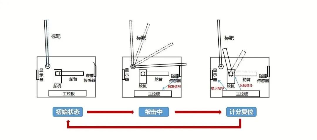
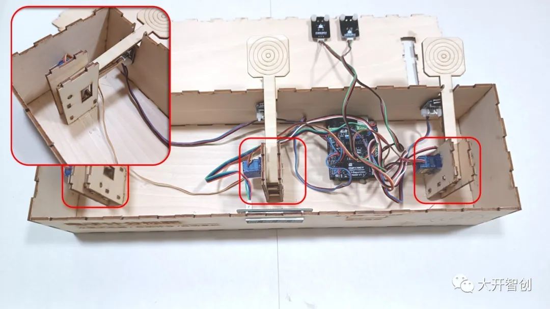
The target is slightly tilted forward when upright to maintain stability and not fall over by itself. When the target is hit, the strong impact causes it to fall and strike a collision sensor, which sends a signal to the main control board. Upon receiving the signal, the main control board performs scoring and display functions, and sends operation commands to the corresponding servo, thus pushing the target back to its original position. Once the servo completes its task, it returns to its original angle.
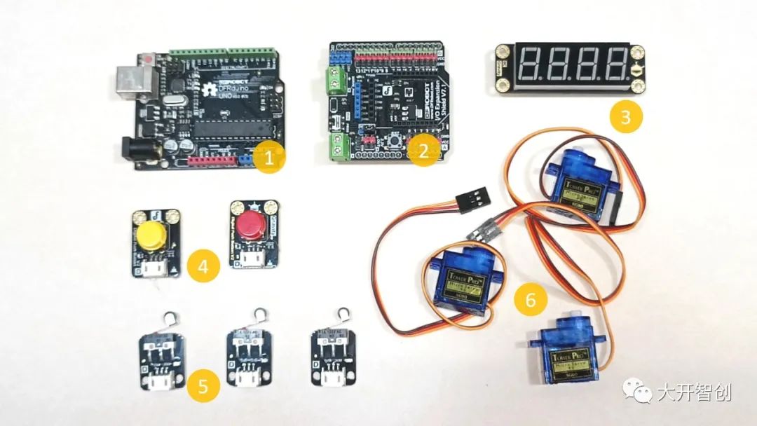
1. Main Control Board: 1 Arduino Uno
2. IO Expansion Board: 1
3. Four-Digit Display Module: 1
4. Digital Buttons: 2
5. Collision Sensors: 3
6. 180° Servos: 3
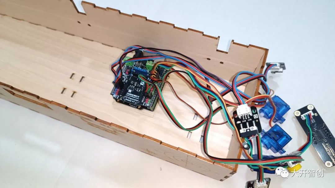
Connect the IO expansion board to the main control board, and connect other electronic modules to the pins of the IO expansion board, as shown in the figure below.
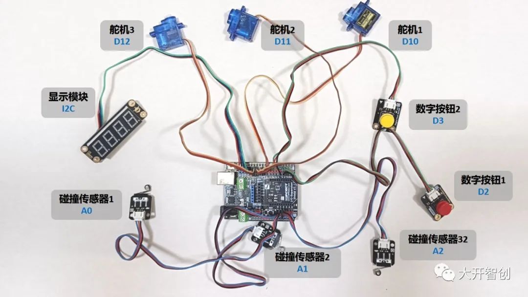
Among them, the display module connects to the I2C pins, the two digital buttons connect to D2 and D3 pins respectively, the three collision sensors connect to A0, A1, and A2 pins respectively, and the three servos connect to D10, D11, and D12 pins respectively.
The program for this project is written using Mind+ software and can be roughly divided into five parts: main program, mode selection program, single-player training subroutine, two-player competition subroutine, and target reset subroutine.
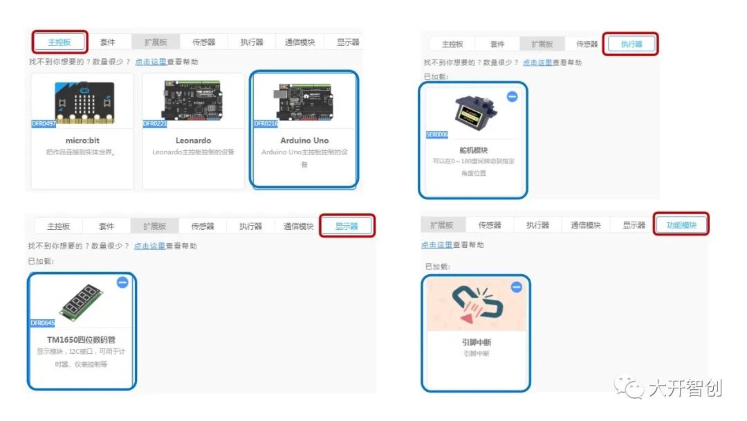
Before writing the program, relevant instruction blocks need to be loaded, which are: [Main Control Board] Arduino Uno, [Actuator] 180° Servo Module, [Display] TM1650 Four-Digit Display, [Function Module] Pin Interrupt.
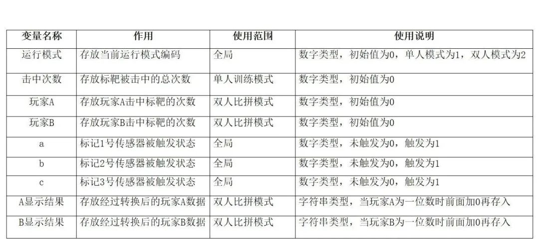
 To achieve the intended functions, some variables are also needed in the program.The variable names and their functions used in this project are shown in the table below.
The main program consists mainly of an initialization part and a main loop part, with the program and explanations shown in the figure below.
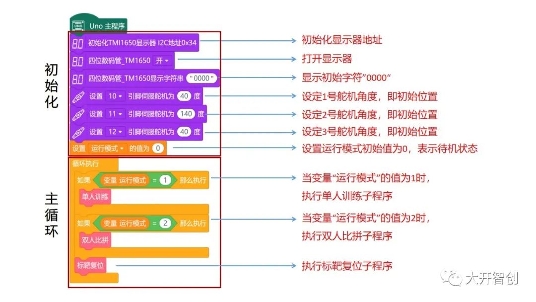
Note: The initial angles of the three servos need to be set according to the actual situation, and repeated testing and modification may be necessary. After assembly, fine-tuning is still required.
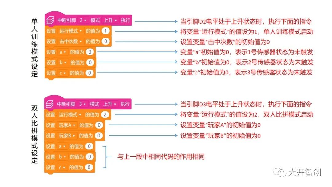
(2) Mode Selection Program
The switching between the two operating modes is done using pin interrupts; pressing the digital button connected to the D2 pin switches to single-player training mode, while pressing the button connected to the D3 pin switches to two-player competition mode. The program and explanation for this part are shown in the figure below.
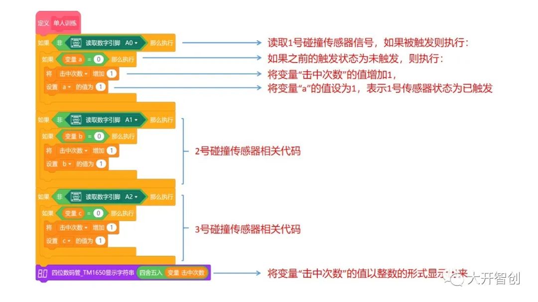
(3) Single-Player Training Subroutine
This subroutine’s function is to detect whether the three collision sensors are triggered; if triggered, it scores and displays. It is important to note that when the sensor is triggered, it will maintain a certain duration, sending multiple trigger signals to the main control board, but only one score will be counted, so variables a, b, and c are used to solve this problem. The program and explanation are shown in the figure below.
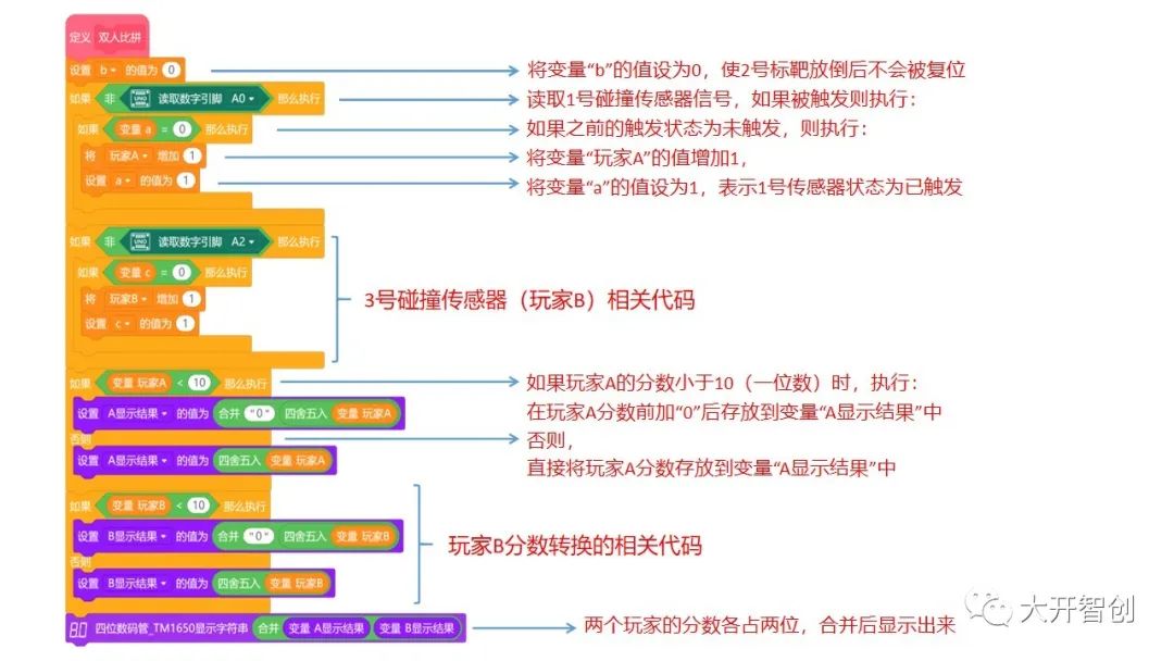
(4) Two-Player Competition Subroutine
This subroutine’s function is to detect whether the 1st and 3rd collision sensors are triggered; if triggered, it scores and displays accordingly. Each player’s score occupies two digits displayed on the screen, and single-digit scores need to be converted. The program and explanation are shown in the figure below.
(5) Target Reset Subroutine
This subroutine’s function is to achieve the automatic reset of the target and the return of the servo arm. A suitable delay can be introduced between the two operations of the servo, but when using a single-threaded main control board, the time should not be set too long to avoid affecting the detection of the next trigger. Additionally, after resetting, the values of variables a, b, and c need to be updated promptly. The program and explanation are shown in the figure below.

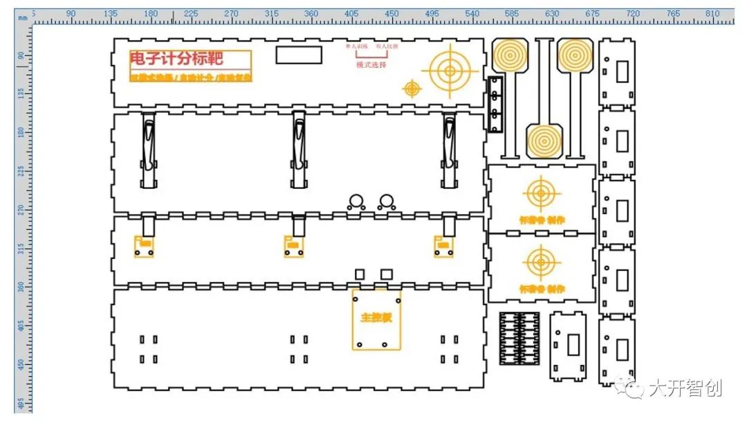
This project has a large form factor, and laser-cut wooden pieces were chosen for the structure and shape. The drawings were created using LaserMaker software, with the material being 3mm thick linden wood. The drawings underwent multiple modifications during the production process, and the final design is shown in the figure below.
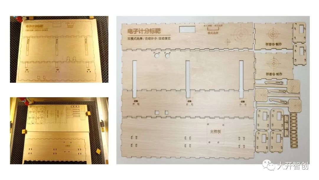
After the drawings are completed, use a laser cutter for cutting and processing. (The image shows the first cut parts; some parts were modified later)
1. Assemble the rectangular box, leaving the top open.

2. Fix the main control board and expansion board to the bottom plate.
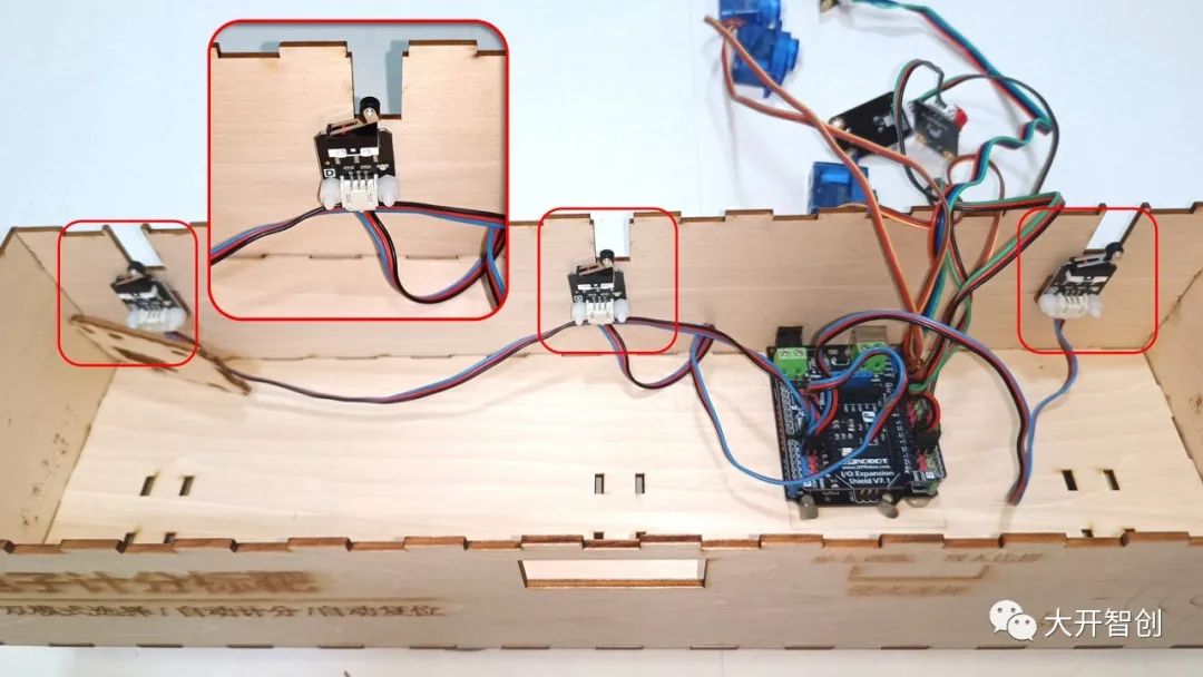
3. Use screws to secure the collision sensors in their designated positions.
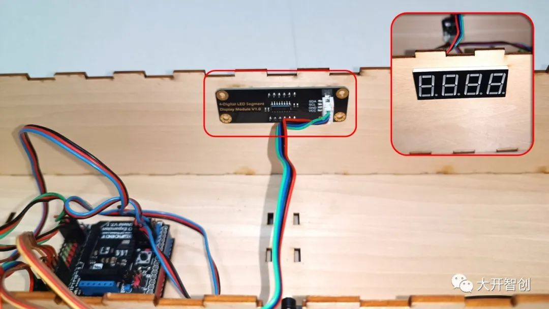
4. Secure the display module in its designated position.
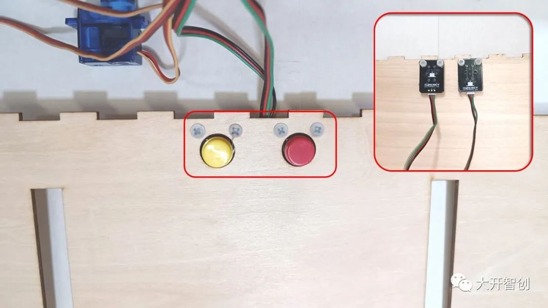
5. Use screws to secure the digital buttons in their designated positions.
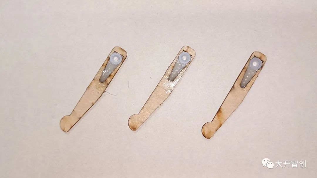
6. Bond the servo’s horn with the wooden arm.
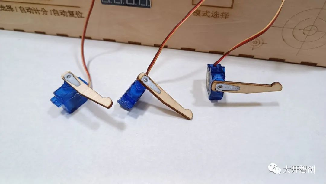
7. Install the arm onto the servo and tighten with screws.
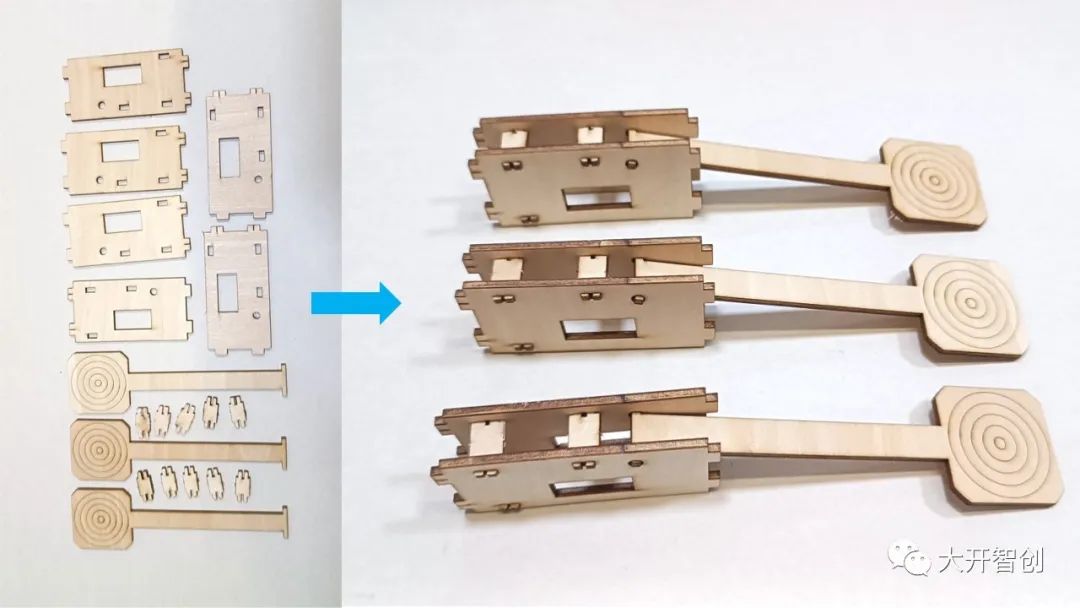
8. Assemble the stand with the target.
9. Install the servo onto the stand.
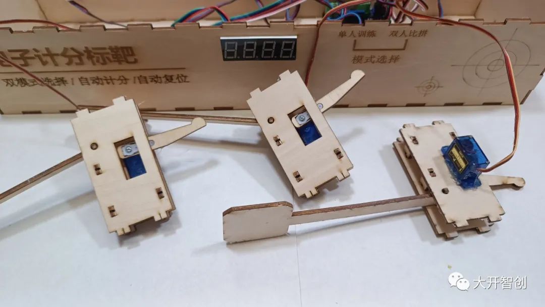
10. Install the stand in the designated position on the base plate.
11. Attach the top plate.
6. Debugging and Optimization
After installation, connect the power supply and test each preset function one by one. Record any issues found promptly, analyze their causes, and improve optimization by modifying the program, changing the shape of structural parts, or installation methods to achieve a more desirable effect.
This project uses electronic modules that are scientifically reasonable, with a simple and effective program design, aesthetically pleasing shape, practical functions, and innovative points, making it a good maker project. However, stability needs improvement, with main issues being: (1) sometimes the force of the target falling is insufficient to trigger effectively; (2) untargeted vibrations can cause the target to fall; (3) during resetting, the target encounters some rebound force, which can sometimes knock it over, causing false triggers. In the future, more complex mechanical structures and other materials can be used in the structural design to enhance stability.
Finally, it is recommended that everyone use a multi-threaded main control board to create this project, as it can achieve more accurate scoring and more flexible resetting methods, as well as expand to include more necessary functions.
The source code and drawing files for this project can be obtained in the following ways:
1. DF Maker Community https://mc.dfrobot.com.cn/ -> Search for “Happy Maker Camp”
2. Knowledge Planet~AI & Maker Education Energy Station
You can directly scan the code to access ↓
-