The new year’s Innovation Competition is in full swing~
To help everyone understand more about this event, the editor has compiled excellent works from 2021 for study and sharing.
Every Monday, we will share award-winning works, so remember to check out the series ~
Team Introduction
Participating Unit: Beijing Institute of Technology Team Name: Flying Tigers Instructor: Li Bin Competition: Arm Cup Participants: Yu Yuxin, Hu Hanqian, Liu Pengyun Award Status: First Prize in National Finals, First Prize in North China Region
1. Project Overview
Video target tracking is one of the important research directions in the field of computer vision, which has high practical value in both military and civilian fields, such as imaging guidance, intelligent transportation, intelligent monitoring, human-computer interaction, and medical diagnosis. However, most related algorithms have high computational complexity, resulting in poor real-time performance. Therefore, achieving real-time target detection and tracking has become one of the key research directions.
This system is based on the Xilinx Artix XC7A100T platform, equipped with a Cortex-M3 core, AMBA bus, and external modules such as GPIO, LCD, OV5640, DDR3, and HDMI. It implements dynamic target detection and real-time tracking functions for camera input images based on hybrid Gaussian modeling and Meanshift algorithms, efficiently running intelligent algorithms, allowing the system to operate in real-time and handle tasks intelligently.
2. System Operation Flow Introduction
a. After powering on the system, initialize all external devices, such as configuring the image size and exposure time of the OV5640 camera. b. When the detection and tracking functions of the system are turned off, the image signal is displayed in real-time via HDMI after being buffered by DDR, serving as a general monitoring function. c. When the detection and tracking functions are turned on, the system detects the position and size of dynamic targets within approximately 1ms after buffering two frames of images in DDR. Then, through the tracking module, it tracks the target’s position in real-time without affecting the image display on HDMI, marking the target’s position with a red box on HDMI and displaying it on the LCD screen. d. Additionally, the system is equipped with a normal operation indicator light, providing real-time feedback on the system’s operational status through a timed LED flashing mechanism.
3. System Architecture
3.1 Architecture Overview
The architecture of this system is shown in Figure 3.1. The processor core uses the Cortex-M3 evaluation core specified by the competition. The system bus adopts the AMBA bus with two layers: the first layer is the AHB bus for overall system space division; the second layer includes an AHB bus and an APB bus, where AHB is used to connect faster peripherals such as OV5640 and HDMI, while the second layer APB is connected to AHB through an adapter module for slower peripherals such as Timer and GPIO.
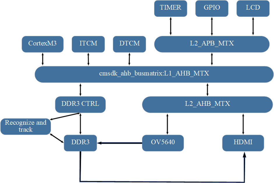 Figure 3.1 Overall System Architecture Diagram
The RGB image signal obtained from the OV5640 is the main data signal processed by the system. Its circulation in the system is shown in Figure 3.2. As can be seen from the figure, this system implements target detection and tracking using a channel accelerator, which is simple and easy to implement, making it friendly for beginners, while significantly accelerating system development efficiency. However, the disadvantage is the poor universality of the module, which requires extensive modifications for different systems. To address this issue, future work will adopt the form of accelerator IPs to improve the universality of the accelerator.
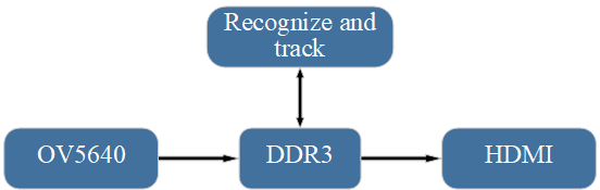 Figure 3.2 System Data Flow Simplified Diagram
3.2 Software and Hardware Function Division
To fully utilize the real-time advantages of FPGA, most functional modules of this work are implemented on the FPGA side, such as the OV5640 related driver module, HDMI display module, DDR3 module, and accelerator module. The ARM side configures a c and h header file for each peripheral that requires trigger control, for parameter configuration and corresponding interrupt event awakening. For example, in the OV5640 module, we set parameters such as image size and maximum exposure frame rate through the software side.
4. Peripheral Mounting
4.1 GPIO Peripheral
This system connects GPIO peripherals on the APB bus, allowing real-time observation of the system’s operation and dynamic debugging through corresponding buttons.
4.2 LCD Peripheral
This system connects an LCD peripheral on the APB bus, primarily used to display the specific position of moving target objects in real-time. The parameters displayed on the LCD screen include the x and y coordinates of the target object’s top-left corner, as well as the width and height of the target object.
4.3 OV5640 Camera Peripheral
This design uses the OV5640 camera from OmniVision. Figure 4.1 shows the detailed block diagram of the camera module.
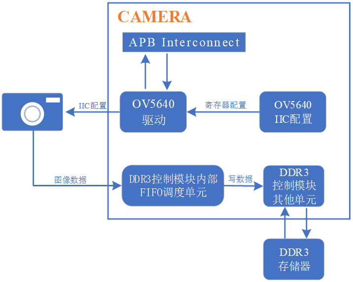 Figure 4.1 Camera Module
After successfully writing a frame of images into DDR, the camera module sends a frame transmission completion interrupt signal to the Cortex-M3 processor and accelerator module, waking them from standby. After storing the first two frames of images, the Cortex-M3 processor temporarily shuts down the image acquisition module, and the accelerator module begins to run the target detection unit. After obtaining the detection results, the Cortex-M3 processor requests the image acquisition module to capture new images and activates the target tracking unit within the accelerator module to execute target tracking.
4.4 DDR3 Storage Peripheral
Due to the complexity of DDR3 timing, directly writing control code for DDR3 is very labor-intensive and difficult to guarantee performance. Therefore, we use the MIG IP core provided by Xilinx to implement DDR read and write. The block diagram of the DDR control module is shown in Figure 4.2.
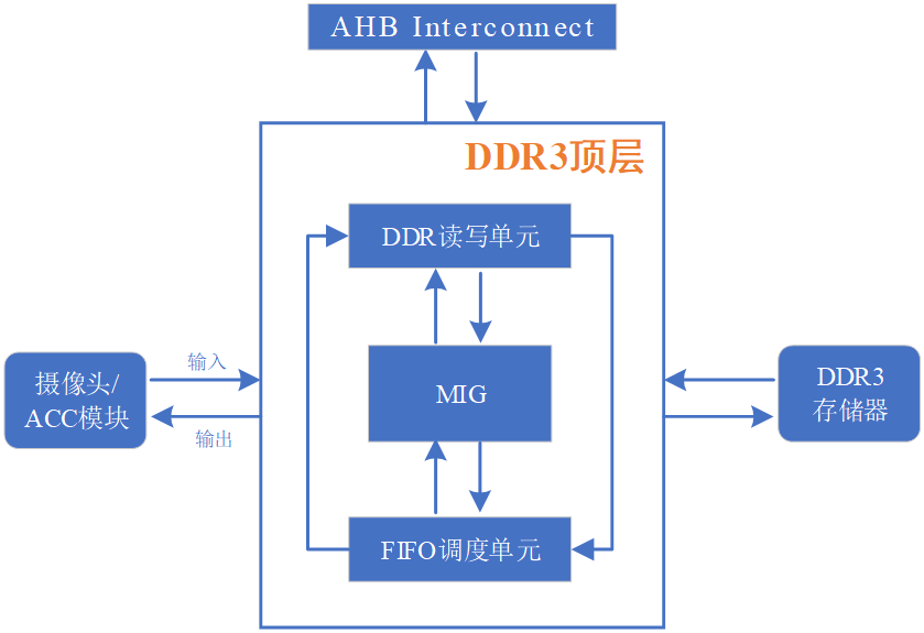 Figure 4.2 DDR Control Module
As shown in the diagram, the DDR read-write unit is responsible for interacting with the MIG module for command and address exchange, switching DDR3 read and write commands and addresses based on the remaining quantity in the FIFO scheduling unit. The FIFO scheduling unit is responsible for clock domain switching and bit-width conversion for input and output data.
4.5 HDMI Display Peripheral
This system uses an HDMI interface, and the module architecture is shown in Figure 4.5. Image data is sent to HDMI via DDR, first processed by the video driver module to generate field synchronization and line synchronization signals corresponding to the image resolution, removing line front and back edges, and field front and back edges to obtain the required display image data. Then, the image data undergoes DVI DC balance encoding; using five times the clock, the image data is converted from serial to parallel, ultimately achieving a tenfold pixel rate for serial data; finally, differential output is performed using TMDS to obtain the display signal.
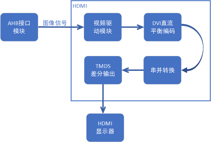 Figure 4.5 HDMI Driver Module
5. Accelerator Design
As shown in Figure 5.1, our team’s accelerator module consists of a target detection unit and a target tracking unit, where the target detection unit uses the hybrid Gaussian modeling algorithm and the target tracking unit uses the MeanShift algorithm.
 Figure 5.1 Accelerator Overall Framework
When the camera completes the data acquisition of the first two frames, the target detection unit is activated, and the accelerator module exchanges data with DDR and calculates relevant parameters. After detection is completed, the target is framed, and the target tracking algorithm is initiated.
5.1 Hybrid Gaussian Modeling Algorithm
Our team uses the hybrid Gaussian background modeling method to obtain the background, suppressing the influence of noise on background elimination and compensating for the shortcomings of frame difference methods. The hybrid Gaussian background modeling algorithm assumes that each pixel point is completely independent, and the value changes of independent pixel points basically conform to a Gaussian distribution over time. By using the probability distribution of pixel values, we determine whether they belong to background pixels. The detailed block diagram is shown in Figure 5.2.
First, initialize the two predefined Gaussian models, initializing parameters in the Gaussian models (pixel Gaussian mean (mean), variance (sd), weight (w), absolute distance (udiff) from pixel to Gaussian mean, and matching flag (match)), and calculate the parameters that will be used. Next, for each pixel in each frame, determine whether it matches a certain model. If it matches, it is assigned to that model, and the model is updated based on the new pixel value. If it does not match, a Gaussian model is created for that pixel, initializing parameters to replace the least likely model in the original model. Finally, select the few most likely models as the background model and extract the target after morphological filtering such as erosion and dilation.
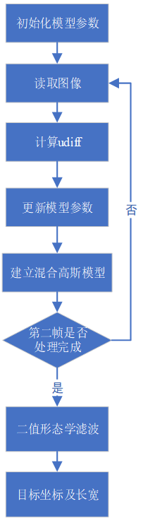 Figure 5.2 Detailed Framework of the Detection Unit
5.2 Meanshift Target Tracking Algorithm
Using the traditional MeanShift algorithm for target tracking. First, initialize the target tracking, which can be obtained through the target detection method to get the bounding box of the initial target to be tracked, or it can be manually selected using a mouse. In this system, the position and size of the initial target rectangle are obtained from the detection accelerator. Then, calculate the histogram distribution of the search window weighted by the weight matrix and calculate the histogram distribution of the corresponding window in frame N using the same method. The search window moves in the direction of maximum density increase based on the principle of maximizing the similarity between the distributions of the two target templates to obtain the true position of the target.
The steps of the MeanShift algorithm tracking are as follows:1. Calculate the probability density of the target template, estimate the position of the target, and determine the width of the kernel window h; 2. Initialize the target position of the current frame and calculate the candidate target template; 3. Calculate the weight values of each point within the current window; 4. Calculate the new position of the target. Studies show that using the Y component in the YUV pixel format, which represents image brightness, can yield better results. Thus, the data used for tracking image targets in the system is derived from RGB converted to YUV.
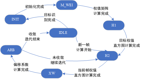 Figure 5.3 Tracking Unit State Transition Diagram
6. Module and System Simulation
6.1 Detection Module Simulation
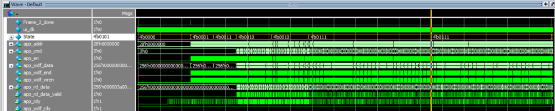
The hybrid Gaussian modeling state machine consists of 11 states. Due to the large number of states and the possibility of state transition errors at a 100MHz clock, Gray code is used for state parameters to avoid such events. The state encoding is as follows: IDLE (4’b0000), W_INIT (4’b0001), SD_INIT (4’b0011), UDIFF_MEAN (4’b0010), U_M_2 (4’b0110), P_UPDATE (4’b0111), P_UP_2 (4’b0101), MODEL_UP (4’b0100), FRAME_JUG (4’b1100), PIXEL_TF (4’b1101), and M_DONE (4’b1111). The state machine simulation is shown in Figure 6.1.
 6.1(a) Transition from IDLE state to P_UPDATE and P_UP_2 state transitions
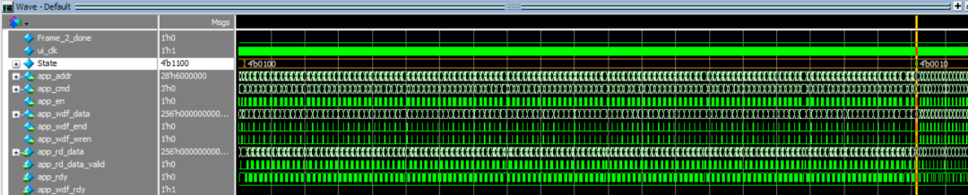 6.1(b) Transition from MODEL_UP state to FRAME_JUG state
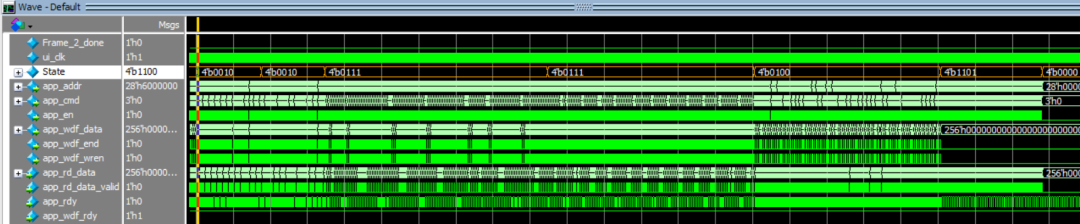 6.1(c) State machine state transition when processing the second frame of the image
Figure 6.1 Simulation of the hybrid Gaussian modeling algorithm state machine transitions. The simulation results of the completion flag are shown in Figure 6.2.
Figure 6.2 Simulation results of the completion flag signal
6.2 Tracking Module Simulation
After simulating through Modelsim, the system tracking data is exported, and corresponding data is collected in Matlab for plotting, as shown in Figure 6.3.
Figure 6.3(a) Horizontal tracking results
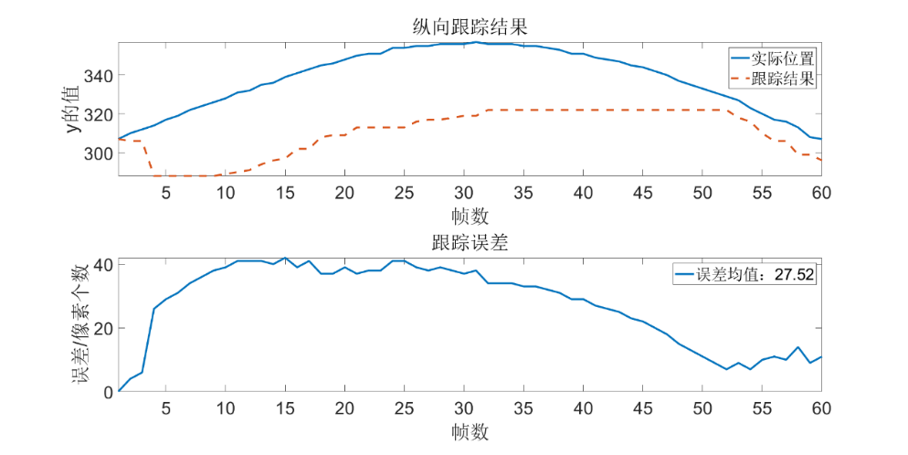 Figure 6.3(b) Vertical tracking results
Figure 6.3 Modelsim simulation results
7. Overall System Testing Results
The overall testing effect of the system is shown in the video, where the system performs well, and there are also demonstrations under more complex backgrounds. We welcome interested students to communicate with us.
8. Competition Experience
Through this competition, we gained a certain understanding of the design of SoC based on the ARM Cortex-M3 core and mastered the relevant design process, further enhancing our professional knowledge level. We also experienced the tense atmosphere of the competition and were honored to work together with over 200 participating teams from universities across the country. Through the presentations during the competition, we gained a better understanding of the current status of the integrated circuit industry in China. We sincerely thank the teachers and staff of the organizing committee for their hard work in this competition!
END


关于安芯教育


安芯教育是聚焦AIoT(人工智能+物联网)的创新教育平台,提供从中小学到高等院校的贯通式AIoT教育解决方案。
安芯教育依托Arm技术,开发了ASC(Arm智能互联)课程及人才培养体系。已广泛应用于高等院校产学研合作及中小学STEM教育,致力于为学校和企业培养适应时代需求的智能互联领域人才。