1. Test Objective
To evaluate the service life of the hub bearing unit under different driving conditions of the vehicle.
2. Test Setup
Use appropriate special fixtures and(or) original automotive components to clamp the hub bearing unit, as shown in Figure2.
The installation positions of the vibration sensor and temperature sensor are determined based on the actual structure of the bearing sample and the fixture. If users have special requirements for the fixture and clamping, they can negotiate with the manufacturer.
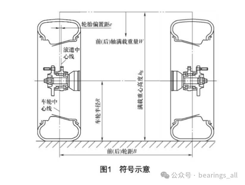
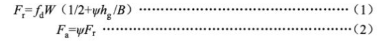
Both radial and axial loads should be applied at the centerline of the wheel, with the radial load line perpendicular to the bearing’s rotation axis, while the axial load line must be parallel to the bearing’s rotation axis, and the loading arm must equal the wheel radiusR. The radial and axial loads are calculated according to formulas(1) and(2), where+Fa represents the forward force, and-Fa represents the reverse force.
3. Pre-Operation of Test Samples
Before the test, apply a radial load ofW/2, with a speed of200r/min, running for2h, this time is not included in the total test time.
4. Test Conditions
The set speed for the durability test is800r/min, with a tolerance of ±5%, and the environmental temperature requirement is20°C ±15°C, with the tightening torque according to user specifications.
5. Test Loads and Cycle Periods
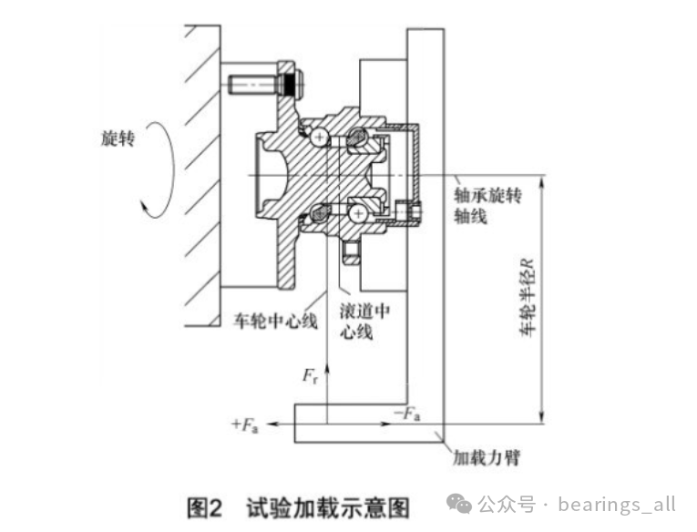
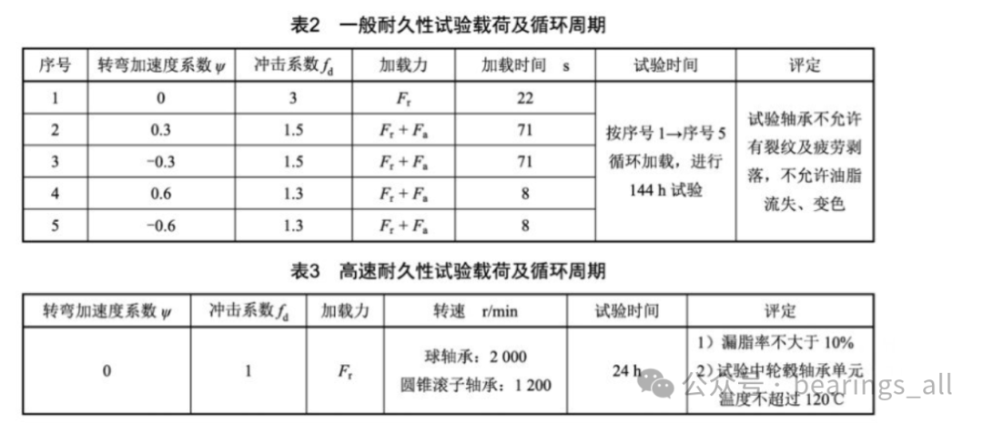
The general durability and high-speed durability test loads and cycle periods are executed according to Table2 and Table3. For high-speed durability tests, weighing must be done before the test, and data recorded. If users have specified test conditions, tests should be conducted according to user conditions.
6. Test Process Recording and Shutdown Requirements
During the test, real-time monitoring of force, speed, vibration, and temperature should be conducted, and parameter values should be recorded and saved at appropriate intervals. The test shutdown is mainly judged by the vibration acceleration value(compared to the initial vibration value), and abnormal temperature is also an additional criterion for shutdown or bearing failure.
7. General Durability Test Results
After the test, cool the test bearing sample, check the rotational flexibility of the bearing by feel, and preliminarily determine if there are any sticking or peeling phenomena. Disassemble the test bearing sample, allowing for the destruction of some parts, and observe if the grease has changed color; clean the bearing parts and check if there is any peeling of the rolling elements and raceways inside the bearing. Throughout the disassembly inspection process, retain overall photos of the bearing after the test, photos of the grease on the inner and outer sides, photos of the cleaned outer ring’s inner and outer raceways(highlighting any peeling locations), photos of the inner raceways on both sides(highlighting any peeling locations), and photos of the steel balls and cages on both sides(highlighting any peeling locations). Check for cracks in the inner ring, outer ring, and flange, and retain necessary photos.
8. High-Speed Durability Test Results
After the test, cool the test bearing sample, retain necessary photos, clean the outer surface of grease leakage, weigh and record data.
9. Evaluation
General durability and high-speed durability tests are evaluated according to the provisions of Table2 and Table3.

References:
JB/T 13353-2017 Hub Bearings Testing and Evaluation Methods for Automotive Hub Bearing Units
 Share
Share Collect
 View
View Like
Like
Reminder : Due to WeChat’s changes in push rules, those who do not frequently click“View” will gradually stop receiving pushes. Please set“Bearing Discussions” as a starred account, and don’t forget to click“Like” and“View” after reading.
Disclaimer: The copyright of this article belongs to the original author. If there are any copyright issues, please contact for deletion!