Today, I will introduce a very simple robot making practice. Although the structure and design are quite simple, it is very helpful for beginners to understand and digest the concepts related to robot control. Robotics is essentially about more advanced sensors, higher chip integration, and more complex drive systems. Therefore, robots are actually not far from us; with a little effort, we can build one ourselves.
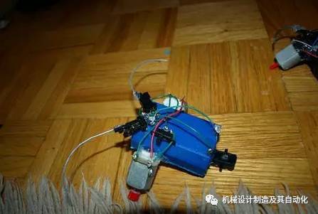
This is a very simple obstacle-avoiding robot, so simple that it doesn’t even use a control chip or drive circuit. It only uses some common items that can be found in our daily lives, yet it achieves basic obstacle avoidance functionality.
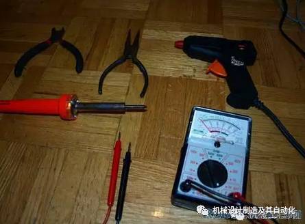
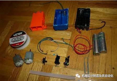
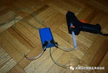
———————————————————-Step 1: Prepare Materials First, we need to prepare all the possible parts we might use. Most of them are taken from old toys, and I believe you can find them in old radios as well. -AA battery holder-> for holding batteries -solder wire-> for soldering -insulated wire-> to connect the battery and motor -2 AA batteries-> to drive the motor -2 1.5V motors (preferably the same specifications)-> to drive the robot -a toggle switch-> as the robot’s switch -2 collision switches -1 to 2 paper clips-> to extend the collision switch’s feelers -glue sticks-> for fixing Step 2: Prepare Tools I borrowed all the necessary tools from my dad. Wire cutters-> for cutting and stripping wires Needle-nose pliers-> for bending paper clips Hot glue gun-> to fix the collision switch and toggle switch to the battery holder Soldering iron-> for soldering multimeter-> to check the battery
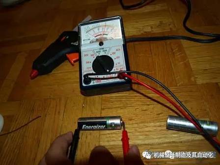
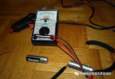
Step 3: Let’s Get Started First, check the battery voltage using the multimeter. If the battery voltage is close to 1.5V, it can be used; otherwise, it’s best to buy new batteries.
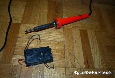
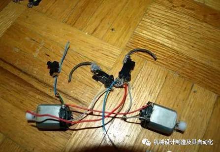
Step 4: Wiring Use the soldering iron and solder wire to solder several wires to the battery holder. It’s best to pay attention to the color of the wires: use red for the positive wire and black for the negative wire.
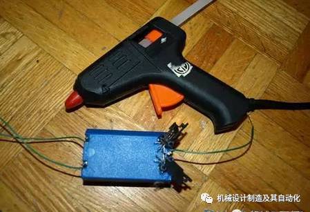
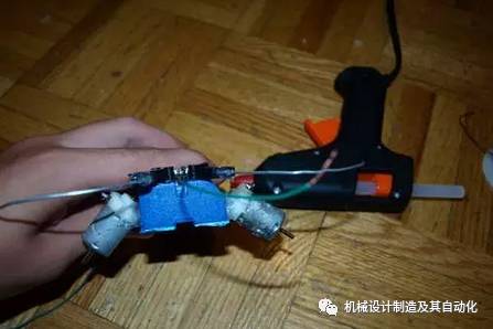
Step 5: Fix the Collision Switch Use hot glue to fix the collision switch to the battery holder at the indicated position.
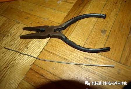
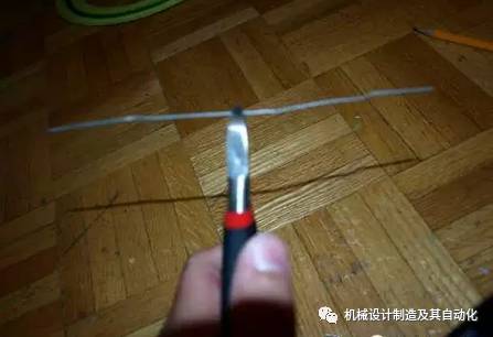
Step 6: Process the Feelers (1) Use the pliers to straighten the paper clips.
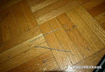
Step 7: Process the Feelers (2) Cut the straightened paper clips to obtain two appropriately sized wires. (You can also use one paper clip to make one feeler; it’s all up to you).
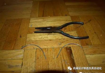
Step 8: Process the Feelers (3) Use the needle-nose pliers to bend the two wires into the shape shown in the picture. Try to make the two wires the same shape; you can bend them together to ensure consistency.
Step 9: Process the Feelers (4) Use hot glue to attach the two feelers to the arms of the collision switch.
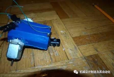
Step 10: Motor Use hot glue to attach the motor to the battery holder, ensuring that the motor forms an angle of about 40 degrees with the battery holder.
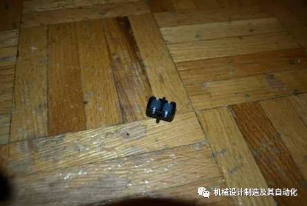
Step 11: Wheels I took this omnidirectional wheel from a toy, but you can buy it at a hardware store. Use hot glue to attach it to the end of the battery holder, forming a three-point support with the two motors. Note that the omnidirectional wheel should be slightly lower than the battery holder so that the battery holder does not touch the ground, allowing the robot to move more smoothly and quickly.
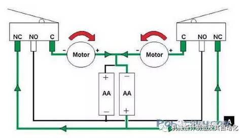
Step 12: Additional Wires Needed You can refer to the schematic diagram I provided later for the specific wiring method.
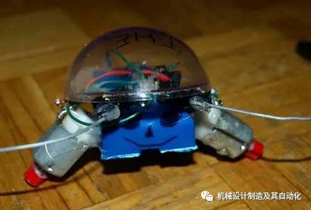
Step 13: Decoration In this step, feel free to express your creativity based on your personal preferences and conditions! You can refer to my decoration plan or unleash your own imagination. I also wrapped some tape around the motor’s rotating shaft to make it run more smoothly.
Step 14: Circuit Schematic When one side of the robot collides with an obstacle, the left or right collision switch closes, causing the right or left motor to reverse, thus allowing the robot to avoid the obstacle. Study the circuit schematic carefully, and you will understand the principle of the robot’s obstacle avoidance.