
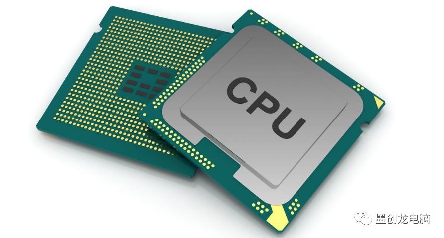
CPU Section
1. CPU Architecture The CPU architecture currently lacks a definitive and authoritative definition. Simply put, it refers to the design scheme of the CPU core. CPUs can generally be classified into various architectures such as X86, IA64, RISC, etc. The CPUs found in personal computers are essentially designed based on the X86 architecture, known as microarchitecture under X86, often referred to simply as CPU architecture. 2. Manufacturing Process The manufacturing process of the CPU refers to the technological level of CPU production. Improving the manufacturing process involves reducing the distance between internal circuits, allowing more functions or stronger performance to be achieved on the same area of silicon wafer. The manufacturing process is measured in nanometers (nm), with the mainstream processes currently being 45nm and 32nm. For ordinary users, more advanced manufacturing processes can lead to lower power consumption and better overclocking potential. 3. Bit Width (32-bit vs. 64-bit CPUs) 32/64-bit refers to the bit width of the CPU. A larger CPU bit width has two benefits: it can process a larger range of data calculations at once and support larger memory capacities. Generally, 32-bit CPUs only support memory up to 4GB, and larger memory capacities cannot be recognized by the system (except for server-grade systems). Hence the emergence of 64-bit CPUs, followed by 64-bit operating systems and software. 4. Clock Speed, External Frequency, and Multiplier The CPU clock speed refers to the working frequency of the CPU during computation. In the era of single-core CPUs, it is the most important indicator of CPU performance, generally measured in MHz and GHz, for example, the Phenom II X4 965 has a clock speed of 3.4GHz. As the speed of CPU development far exceeds that of memory, hard drives, and other components, the concepts of external frequency and multiplier were introduced, with the relationship being: Clock Speed = External Frequency x Multiplier. What we commonly refer to as overclocking involves manually increasing the external frequency or multiplier to boost the clock speed. 5. Number of Cores and Threads Currently, mainstream CPUs have dual-core, triple-core, and quad-core configurations, with six-core CPUs released in 2010. Increasing the number of cores is intended to increase the number of threads, as the operating system executes tasks via threads. Generally, there is a 1:1 correspondence, meaning a quad-core CPU typically has four threads. However, after Intel introduced Hyper-Threading technology, the relationship between cores and threads became 1:2. 6. Multimedia Instruction Set MMX, 3DNOW!, and SSE are all multimedia extension instruction sets for CPUs that accelerate CPU computations, provided that there is software support. If software is optimized for the CPU’s multimedia instruction set, the computational speed of the CPU can be further enhanced. 7. Virtualization Technology The CPU’s virtualization technology (Virtualization Technology, abbreviated as VT) allows a single CPU to simulate multiple CPUs and enables a platform to run multiple operating systems simultaneously, with applications running in independent spaces without interference, significantly improving work efficiency.
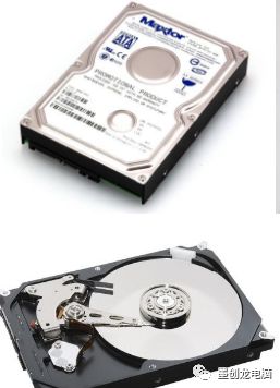
Hard Disk Section
1. Capacity Calculation Method In computers, binary is used, so the capacity calculation in the operating system is based on powers of 1024, i.e., 1024 bytes = 1KB, 1024KB = 1MB, 1024MB = 1GB; whereas hard disk manufacturers calculate capacity based on powers of 1000, i.e., 1000 bytes = 1KB, 1000KB = 1MB, 1000MB = 1GB. This difference in base leads to a “shrinkage” of hard disk capacity. 2. Rotational Speed Rotational speed refers to the speed at which the hard disk’s motor spindle rotates, or the maximum number of revolutions the hard disk platters can complete in one minute. The faster the hard disk’s rotational speed, the quicker it can locate files, thereby improving data transfer speed. 3. Single-Platter Capacity The single-platter capacity is one of the critical parameters for hard disks, to some extent determining the quality level of the hard disk. A hard disk is composed of multiple storage platters, and the single-platter capacity refers to the maximum amount of data that a single platter can store. 4. Number of Platters Platters are the media that carry data storage in hard disks. A hard disk consists of multiple stacked platters, separated by spacers. The platters are made of durable materials with a magnetic substance attached, and their surfaces are processed to be very smooth. The more platters a hard disk has, the thicker it is, and the more heat it generates. 5. Random Seek Time (in milliseconds) The difference in rotational speed directly reflects performance differences in random read/write seek times. The lower the value of random seek performance, the better it is, and it is one of the most directly experienced performance metrics in daily hard disk applications. Whether it’s booting Windows, reading/writing a large number of fragmented files, or the startup time of various software, all have a direct relationship with random read/write times. 6. Perpendicular Recording Technology Perpendicular recording refers to the method of recording where the SN direction of each recording unit is horizontal to the platter, as opposed to longitudinal recording. Perpendicular recording technology effectively overcomes the superparamagnetic effect by utilizing thickness, thereby significantly increasing disk density and replacing longitudinal recording technology. 7. Solid State Drives Solid State Drives (SSD), also known as electronic disks or solid-state electronic drives, utilize two types of storage media: one uses flash memory (FLASH chips) and the other uses DRAM. SSDs have the same interface specifications and definitions, functions, and usage methods as traditional hard drives, but due to the absence of rotating media, they exhibit excellent shock resistance. Furthermore, their random read/write capabilities far surpass those of traditional hard drives.

Memory Section
1. Types of Memory Currently, the memory used in desktop platforms includes DDR1/DDR2/DDR3, with DDR1 being mostly obsolete, while DDR2 and DDR3 are the mainstream types. The three types of DDR memory are not compatible with each other, from the memory controller to the memory slots. Even on some Combo motherboards that support both types, the two specifications cannot work simultaneously; only one type of memory can be used. 2. Capacity The memory capacity refers to the storage capacity of the memory module and is a key parameter of the memory. Memory capacity is measured in MB and can be abbreviated as M. The capacity of memory is generally in powers of 2, such as 512MB, 1GB, 2GB, etc. Generally, the larger the memory capacity, the better it is for system operation. 3. Frequency The memory clock speed, like the CPU clock speed, is habitually used to indicate the speed of the memory, representing the highest working frequency that the memory can achieve. Memory clock speed is measured in MHz (megahertz). A higher memory clock speed generally indicates faster memory. The mainstream memory frequencies currently are 800MHz for DDR2 memory and 1333MHz for DDR3 memory. 4. Memory Controller The memory controller is an essential component within the computer system that controls memory and facilitates data exchange between memory and the CPU. The memory controller determines the maximum memory capacity that the computer system can use, the number of memory banks, memory types and speeds, memory chip data depth, and data width, etc. In other words, it determines the memory performance of the computer system, thus significantly impacting the overall performance of the computer system. 5. Memory Timing Parameters Memory timing (CL) consists of four parameters: “CL-tRCD-tRP-tRAS”, which reflect the waiting time from when the CPU receives the instruction to read memory data until it actually starts reading the data. It is evident that, for memory of the same frequency, those with lower CL settings have a speed advantage. Generally, when checking the timing parameters of memory, such as the sequence of numbers “8-8-8-24”, these numbers correspond to the parameters “CL-tRCD-tRP-tRAS”. 6. Memory SPD SPD (Serial Presence Detect) is an 8-pin EEPROM (Electrically Erasable Programmable Read-Only Memory), with a capacity of 256 bytes, mainly storing information related to the memory, such as capacity, chip manufacturer, memory module manufacturer, operational speed, etc. The contents of SPD are generally written by the memory module manufacturer. Motherboards that support SPD automatically detect the information in SPD at startup and set the memory working parameters accordingly.
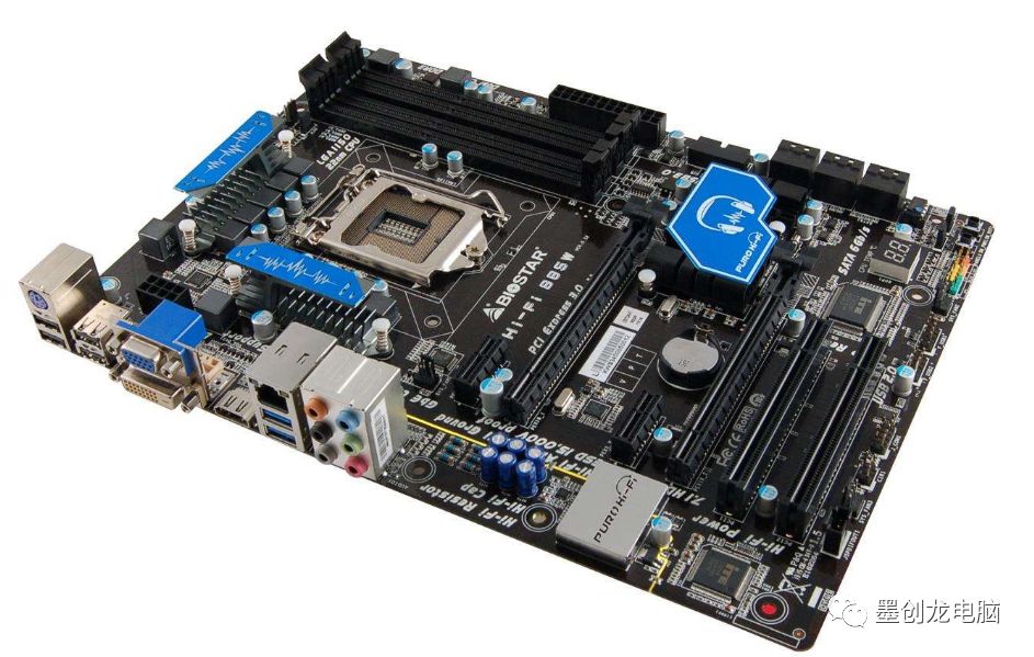
Motherboard Section
1. Chipset The chipset is the core of the motherboard circuitry. To some extent, it determines the level and quality of the motherboard. It is a collective term for the “southbridge” and “northbridge”, integrating complex circuits and components into a few chips as much as possible. 2. Northbridge Chip The northbridge chip is responsible for communication with the CPU and controls memory and AGP data transmission within the northbridge, providing support for CPU types and clock speeds, the system’s front-side bus frequency, memory types and maximum capacities, AGP slots, ECC error correction, etc. The integrated chipset’s northbridge chip also integrates the display core. 3. Southbridge Chip The southbridge chip is an important component of the motherboard chipset, responsible for communication between I/O buses, such as PCI bus, USB, LAN, ATA, SATA, audio controllers, keyboard controllers, real-time clock controllers, advanced power management, etc. It is generally located further from the CPU socket on the motherboard, near the PCI slots, as this layout is advantageous for wiring due to the many I/O buses it connects. 4. BIOS BIOS (Basic Input/Output System) is the full name for ROM-BIOS, which is a set of programs stored in the computer to provide the most basic and direct hardware control for the computer. It acts as a hub between software programs and hardware devices, essentially serving as a “converter” or interface between hardware and software programs (although it is also just a program), responsible for addressing the immediate demands of hardware and executing specific operations as required by software. 5. CMOS CMOS stands for Complementary Metal-Oxide-Semiconductor. It refers to a type of technology used to manufacture large-scale integrated circuit chips or the chips produced using this technology. Here, it usually refers to a writable RAM chip on the computer motherboard. It stores real-time clock information and hardware configuration information for the computer system. When the system powers on and boots up, it reads the CMOS information to initialize the status of the various components of the machine. 6. MOSFETs MOSFET, known in Chinese as field-effect transistors, are commonly referred to as MOS transistors. This black square acts as a switch in the power supply circuit, controlled by gate voltage. Each phase’s upper and lower bridges are alternately conducting, charging and discharging the output choke of that phase, thus obtaining a stable voltage at the output end. 7. All-Solid Capacitors In addition to aluminum electrolytic capacitors, solid capacitors are commonly found in the CPU power supply section. The solid capacitors we commonly see are aluminum-polymer capacitors, a new type of capacitor. Compared to regular aluminum electrolytic capacitors, they are less affected by temperature, have better high-frequency characteristics, lower ESR, and generate less heat.
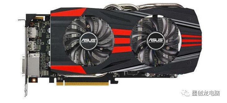
Graphics Card Section
1. Graphics Processing Unit (GPU) The processor of the graphics card is called the Graphics Processing Unit (GPU), which is similar to the computer’s CPU. However, the GPU is designed specifically for executing complex mathematical and geometric calculations necessary for graphics rendering. Some of the fastest GPUs have more transistors than typical CPUs. GPUs generate a lot of heat, so they are usually equipped with heatsinks or fans. 2. Video Memory Video memory, abbreviated as VRAM, is primarily used to temporarily store the data that the display chip needs to process and the data that has been processed. The more powerful the graphics core, the more video memory is needed. 3. API DirectX and OpenGL are both application programming interfaces, abbreviated as API. APIs provide instructions for complex tasks (such as 3D rendering) to help hardware and software communicate more efficiently. Developers optimize games that heavily use graphics for specific APIs, which is why the latest games often require updated versions of DirectX or OpenGL to run correctly. 4. DirectX DirectX is not just a graphics API; it is a versatile API developed by Microsoft, which includes components such as Direct Graphics (Direct 3D + Direct Draw), Direct Input, Direct Play, Direct Sound, Direct Show, Direct Setup, and Direct Media Objects, providing a complete multimedia interface solution. 5. Stream Processor Units Before the advent of DX10 graphics cards, the term “stream processor” did not exist. The GPU consists of pipelines, which are divided into pixel pipelines and vertex pipelines, with a fixed number. The vertex pipeline is primarily responsible for 3D modeling, while the pixel pipeline handles 3D rendering. Since their numbers are fixed, when a game scene requires a lot of 3D modeling but not much pixel processing, it can lead to resource tightness in the vertex pipeline while the pixel pipeline remains largely idle, and vice versa. In such cases, the concept of “unified shader architecture” was introduced during the DX10 era, where graphics cards eliminated the traditional “pixel pipeline” and “vertex pipeline” in favor of stream processor units that can perform both vertex and pixel operations. 6. Video Memory Width The video memory width indicates the number of bits of data that can be transmitted in one clock cycle. The larger the width, the greater the amount of data that can be transmitted at once, making it an important parameter of video memory. Video Memory Bandwidth = Video Memory Frequency x Video Memory Width / 8. 7. Video Memory Speed (in ns) Video memory speed is generally measured in ns (nanoseconds). Common video memory speeds include 1.2ns, 1.0ns, 0.8ns, etc.; the smaller the number, the faster and better the speed. The theoretical working frequency of video memory can be calculated using the formula: Effective Working Frequency (MHz) = 1000 / (Video Memory Speed x n) (where n varies by video memory type; for GDDR3 memory, n=2; for GDDR5 memory, n=4).
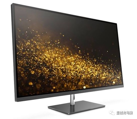
Monitor Section
1. Brightness (in cd/m²) The academic unit for brightness is cd/m² (candela per square meter), for example, 250cd/m² means the brightness equivalent to lighting 250 candles in a 1 square meter area. The optimal brightness for human eyes is 150cd/m². Since the brightness of monitors can be affected by external light, it is necessary to manufacture monitors with higher brightness. The maximum brightness is usually determined by the cold cathode ray tube (backlight), and the brightness values for TFT-LCDs generally range from 200 to 350cd/m². 2. Contrast Ratio The contrast ratio is defined as the maximum brightness value (full white) divided by the minimum brightness value (full black). The larger the ratio, the better the monitor. The contrast ratio of LCD monitors can reflect whether they can display rich gradations and layers in images. A higher contrast ratio leads to sharper images, clearer visuals, and more vivid colors with a richer sense of depth. 3. Dynamic Contrast Ratio The dynamic contrast ratio is based on dynamic backlight adjustments, varying the backlight brightness according to the brightness of the image. In reality, this so-called dynamic contrast ratio can only be derived from such testing methods. Overall, dynamic contrast ratios are somewhat exaggerated by manufacturers and have little practical significance for overall performance. 4. Color Count The color count indicates the maximum number of colors that can be displayed on the screen. We typically use 16.7M to represent true 24-bit color (8-bit panel) and 16.2M for a 6-bit panel. The actual visual effect difference between the two is not significant; currently, high-end LCD monitors predominantly feature 16.7M colors. 5. Response Time Response time is usually measured in milliseconds (ms) and refers to the speed at which an LCD monitor responds to input signals, i.e., the time it takes for liquid crystal particles to change from dark to bright or from bright to dark, comprising “rise time” and “fall time”. Typically, the response time discussed refers to the sum of the two. For general users, purchasing a product with an 8ms response time usually suffices for daily applications, while gamers may prefer products with 5ms or faster response times. 6. Viewing Angle The viewing angle of an LCD monitor refers to the range of angles from which users can clearly see the monitor’s display. Viewing angles can be divided into horizontal and vertical aspects. The horizontal viewing angle is centered on the vertical axis of the LCD, allowing users to see the image clearly while moving left or right. Currently, mainstream TN panels can achieve viewing angles of around 170°/160° (horizontal/vertical), while LCDs using wide viewing angle panels (IPS/PVA) generally exceed 178 degrees.
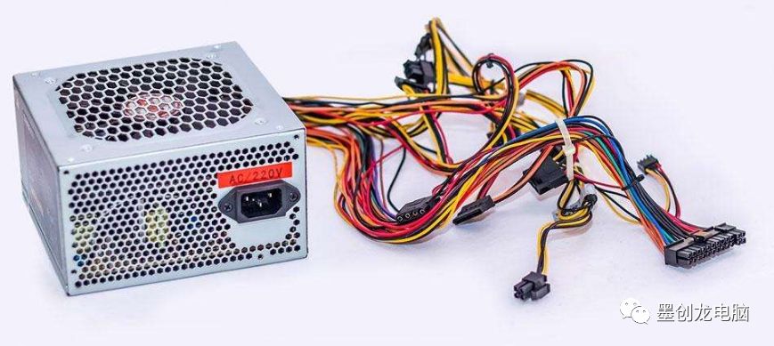
Power Supply Section
1. Rated Power The rated power is the power marked by the power supply manufacturer according to the standards set by Intel, and there is no specific calculation formula. It generally refers to the effective power that can be continuously output, which is the power that the power supply can stably output under normal working conditions. Rated power is the most important parameter specification of a power supply. 2. Maximum (Peak) Power The maximum (peak) power refers to the maximum power that the power supply can output for a short time. Since the power supply cannot maintain stable operation at maximum (peak) power for extended periods, it holds little significance for consumers. 3. Active/Passive PFC PFC (Power Factor Correction) refers to the relationship between effective power and total power consumption (apparent power), which is the ratio of effective power to total power consumption (apparent power). Currently, there are two types of PFC: passive PFC (also known as passive PFC) and active PFC (also known as active PFC). 4. ATX Power Supply Specification The ATX specification is a standard for motherboard and power supply structure established by Intel in 1995, with ATX being the abbreviation for AT Extend. Currently, the commonly accepted power supply standard in China is the ATX 12V standard, which can be divided into multiple versions such as ATX12V 1.2, ATX12V 1.3, ATX12V 2.0, ATX12V 2.2, ATX12V 2.3, and ATX12V 2.31. When selecting a power supply, it is advisable to choose one with a higher specification version. 5. 80 PLUS Certification 80 PLUS is a reward policy implemented by Ecos Consulting in the United States for power supply manufacturers. To obtain 80 PLUS certification, a power supply must have conversion efficiency greater than 80% under 20%, 50%, and 100% load conditions. Once certified, the power supply will receive additional subsidies during sales. 6. 3C Certification 3C, which stands for CCC, is the abbreviation for China Compulsory Certification. There are currently four versions of the 3C certificate: CCC(S) safety certification, CCC(S&E) safety and electromagnetic compatibility certification, CCC(EMC) electromagnetic compatibility certification, and CCC(F) fire safety certification. Among them, CCC(S) only indicates compliance with safety standards. The currently used standard is CCC(S&E), which imposes safety and electromagnetic compatibility requirements on power supplies. Seeing the CCC(S&E) mark on a power supply means that it has passed 3C certification, which is a standard that all power supply products must meet. 7. CE Certification CE is an abbreviation derived from the French “Communauté Européenne”, meaning European Union. The CE mark is a safety certification mark, similar to “3C in Europe”. Products with the CE mark can be sold in EU member states without having to meet the requirements of each individual member state, thus allowing for the free circulation of goods within the EU member states.
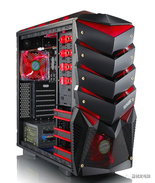
Case Section
1. ATX Case The ATX case has a vertical structure and unifies the I/O interface to one wide side (30.5cm), forming a “back panel” style. Additionally, ATX specifies that the hot air from the CPU cooler must be expelled outside, enhancing cooling while reducing dust accumulation inside the case. ATX cases can accommodate more components, generally having four hardware slots and three or more optical drive bays, with a more spacious internal structure. Currently, the mainstream case products on the market adopt this structure. 2. ABS Engineering Plastic The plastic panel at the front of the case is the part most frequently touched by users, and the most common material for this part is ABS engineering plastic and ordinary plastic. ABS engineering plastic is characterized by impact resistance, high toughness, non-toxic, and resistance to fading, allowing it to maintain its appearance color for a long time. 3. Electrogalvanized Steel Plate (SECC) The zinc layer on electrogalvanized steel is applied through electroplating, providing fingerprint resistance and corrosion resistance while retaining the workability of cold-rolled plates. Most domestic case manufacturers use SECC material. 4. Hot-Dip Galvanized Steel Plate (SGCC) The zinc layer on steel plates is applied through hot-dip, making it a high-quality steel material with superior corrosion resistance. Currently, no steel mill in China can produce this material, so most of it is imported. 5. CAG1.1 Standard (also known as 38°C Case) The 38°C is a temperature index regarding cases. In 2003, Intel introduced the stringent CAG1.1 standard, which states that at a room temperature of 25°C, the average temperature at four points 2CM above the CPU cooler must not exceed 38°C. Cases that meet this standard are referred to as 38°C cases. Simply put, a 38°C case is designed according to Intel CAG 1.1 specifications and tested through TAC 1.1 standards. 6. TAC 2.0 Standard (also known as 40°C Case) TAC 2.0 is the third case standard led by Intel, following CAG 1.0 and CAG 1.1, mainly designed to address the increased heat generation from CPU and GPU heat sources. The design involves removing the airflow cover from the side panel, creating openings in a 150mm long and 110mm wide area directly above the CPU to the PCI-E graphics card slot. This design ensures that the temperature at the CPU fan intake does not exceed 5°C above the room temperature, meaning at 35°C room temperature, it should not exceed 40°C, hence referred to as a 40°C case. 7. EMI Spring Clips/Contacts EMI spring clips and contacts on the case enhance the tight contact between various metal components of the case, allowing them to connect into a single metal cavity, making it difficult for electromagnetic radiation to leak out, thus protecting users from electromagnetic radiation. Cases with good radiation protection design incorporate numerous EMI springs and contacts at the base, front panel, top cover, rear panel edges, and even at power interfaces.
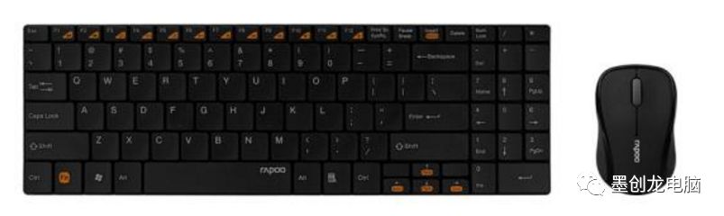
Mouse and Keyboard Section
1. Mouse Resolution (DPI/CPI) The resolution of a mouse is typically measured in DPI or CPI, where DPI stands for dots per inch, meaning the number of pixels per inch. CPI stands for counts per inch, indicating the sampling rate per inch. The two values are generally very close, with DPI being relatively higher than CPI at higher values. 2. Refresh Rate (FPS) The unit for describing refresh rate is FPS, which indicates how many times per second the mouse reads data from the optical sensor. Optical mice rely on continuous scanning to detect the direction of mouse movement. However, if the FPS is low during high-speed movement, it can lead to lost tracking. 3. Report Rate (Polling Rate) The mouse report rate (also known as polling rate) refers to the transmission frequency between the mouse MCU (Microcontroller Unit) and the computer. For example, a report rate of 125Hz means the MCU can send data to the computer every 8ms, while 500Hz means sending data every 2ms. 4. Ergonomics Ergonomics refers to the design principle of making tools as compatible as possible with the natural shape of the human body, allowing users to work without needing to actively adapt their bodies and minds, thus minimizing fatigue caused by tool use. Mouse ergonomics encompasses not only shape design but also button placement, labeling, and other aspects. 5. 2.4G Wireless Transmission For wireless mice and keyboards, there are three types of wireless transmission modes: 27MHz, 2.4G, and Bluetooth. The 2.4G mode is currently the mainstream, typically with an effective distance of 10 meters and requires a wireless receiver. The reason it is called “2.4G” instead of “2.5G” is that the technology uses the frequency range of 2.4-2.485GHz ISM, which is generally free to use without authorization in most countries, facilitating product proliferation. 6. Mechanical Keyboard Mechanical keyboards generally use principles similar to metal contact switches to conduct or break contacts. In practice, there are many structural forms for mechanical keys, with the most common being the cross-contact type. Their advantages include durability and reliability, mainly used in high-end servers and environments with prolonged usage, such as banks and programming industries. 7. Scissor Switch “X-Structure” The “X-structure”, also known as scissor switch architecture, exhibits balanced keystroke force across five testing points (top left, top right, bottom left, bottom right, and center) compared to traditional keyboards, which have larger and uneven keystroke forces.
Audio Section
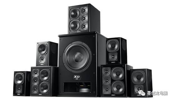
1. 2.0/2.1/4.1/5.1/6.1/7.1 Speakers For multichannel active speakers with a subwoofer, the preceding number (2 or 4, 5, 7) represents the number of surround speakers, while the following “.1” indicates a dedicated subwoofer channel capable of producing ultra-low frequencies ranging from 20-120Hz. For instance, a “2.1 speaker” indicates a system with two surround speakers and one subwoofer. Specially, a “2.1+1” indicates an additional standalone amplifier. 2. Crossover Generally, different diameters of driver units are suited for different frequency applications, and using only one unit is challenging to achieve ideal playback results. Therefore, most speakers adopt a minimum two-way crossover design. The crossover uses LC oscillating circuit components to achieve signal diversion based on different frequency signals. The crossover point refers to the minimum frequency value for the high-pass filter circuit in ideal conditions or the maximum frequency value for the low-pass filter circuit. 3. Sensitivity For amplifiers, sensitivity generally refers to the input voltage required to achieve rated output power or voltage, also known as input sensitivity; for speakers, sensitivity indicates how many decibels of sound pressure level can be produced at a distance of 1 meter from the speaker when 1W input power is applied. 4. Sound Field The sound field refers to the space occupied by the elastic medium where sound waves exist. In actual review articles, we often describe the directivity performance of speakers based on the width of the sound field they reflect. It indicates the width of the sound we can perceive while listening, while depth refers to the depth of the sound field. 5. Bass Reflex Structure Many speakers utilize bass reflex structures, with the design philosophy based on the theory of sound wave superposition to produce higher sound pressure. The speaker cabinet releases sound waves from the rear through a reflex port, which, after reflecting off walls, combines with direct sound waves from the speaker to generate higher-energy sound waves. 6. Signal-to-Noise Ratio The signal-to-noise ratio refers to the background noise, abbreviated as “noise floor”, which is the additional signal added to the output signal due to hardware reasons. It directly relates to the circuit design and wiring of the audio system, interference resistance, and isolation between stages, indicating the purity of sound playback and whether the quality of the speaker affects sound purity. 7. Amplifier An amplifier is a circuit assembly that amplifies audio signals. Depending on the amplification elements, it can be classified into tube amplifiers and solid-state amplifiers. In multimedia active speakers, most use amplifier ICs for power amplification; this type of amplifier is categorized as a “solid-state” amplifier (though it cannot be strictly classified as such since it is merely a circuit).