Author: wuchao226 Link: https://www.jianshu.com/p/8e35c3883035
OSI Seven-Layer Model
OSI adopts a layered structured technology, which is divided into seven layers: Physical Layer, Data Link Layer, Network Layer, Transport Layer, Session Layer, Presentation Layer, Application Layer.
TCP/IP Model
The OSI model is relatively complex and academic, so the TCP/IP model we actually use is divided into 4 layers: Link Layer, Network Layer, Transport Layer, Application Layer. The correspondence between the two models is shown in the figure below:
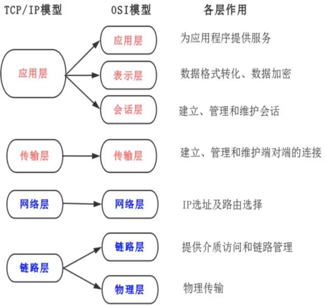
No matter what model is used, each abstract layer is built on the services provided by the lower layer and provides services for the higher layer.
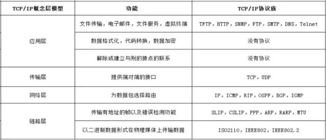
TCP/IP Protocol Family
The abbreviation of Transmission Control Protocol/Internet Protocol, in Chinese it is called 传输控制协议/因特网互联协议, is the most basic protocol of the Internet and the foundation of the international Internet network, consisting of the IP protocol of the network layer and the TCP protocol of the transport layer. The protocol adopts a four-layer hierarchical structure. However, in many cases, it is a collective term for the protocol group that must be used when communicating via IP.
Data in TCP/IP Network Transmission
In each layer, a header is added to the data being sent, which contains necessary information for that layer, such as the destination address and protocol-related information. Typically, the information provided for the protocol is the packet header, and the content to be sent is the data. From the perspective of the next layer, all packets received from the previous layer are considered as data for this layer.
Data packets transmitted in the network consist of two parts: one part is the header used by the protocol, and the other part is the data passed from the previous layer. The structure of the header is detailed in the specific specifications of the protocol. The header of the data packet clearly indicates how the protocol should read the data. Conversely, by looking at the header, one can understand the necessary information of the protocol and the data to be processed.
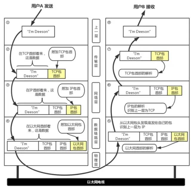
1. Application Program Processing: The application program will first perform encoding, which corresponds to the presentation layer function of OSI; after encoding, the email may not be sent immediately. This management function of when to establish a communication connection and when to send data corresponds to the session layer function of OSI.
2. TCP Module Processing: TCP is responsible for establishing connections, sending data, and disconnecting based on application instructions. TCP provides reliable transmission that ensures data sent from the application layer reaches the other end smoothly. To achieve this, a TCP header is added to the front of the application layer data.
3. IP Module Processing: IP combines the TCP header and TCP data sent by TCP as its own data and adds its own IP header to the front of the TCP header. After the IP packet is generated, it refers to the routing control table to determine the route or host to which this IP packet should be sent.
4. Network Interface (Ethernet Driver) Processing: The IP packet from IP is data for Ethernet. An Ethernet header is added to this data, and after processing, the generated Ethernet data packet is transmitted to the receiving end through the physical layer.
5. Network Interface (Ethernet Driver) Processing: After the host receives the Ethernet packet, it first finds the MAC address from the Ethernet packet header to determine whether it is a packet sent to itself. If not, the data is discarded. If it is a packet sent to itself, it determines the data type from the type in the Ethernet packet header and then passes it to the corresponding module, such as IP, ARP, etc. Here, the example is IP.
6. IP Module Processing: After the IP module receives the data, it also performs similar processing. It determines whether the IP address in the packet header matches its own IP address. If it matches, it sends the data to the corresponding module, such as TCP or UDP, based on the protocol type in the header. Here, the example is TCP. Additionally, in cases with routers, the receiving end address is often not its own address. In this case, it needs to refer to the routing control table to investigate which host or router to forward the data to.
7. TCP Module Processing: In the TCP module, it first calculates the checksum to determine whether the data has been corrupted. Then it checks whether the data is received in order. Finally, it checks the port number to identify the specific application program. Once the data is completely received, it is passed to the application program identified by the port number.
8. Application Program Processing: The receiving end application program will directly receive the data sent by the sending end. It will parse the data and display the corresponding content.
TCP and UDP
The Internet Protocol IP is a very important protocol in TCP/IP. It is responsible for adding IP addresses to the data (the address of the host sending it (source address) and the address of the host receiving it (destination address)) and other data to determine the transmission target.
Both TCP and UDP are transport layer protocols, and the transport layer mainly provides end-to-end communication for application programs on two hosts.
However, the most significant difference between TCP and UDP is that TCP provides a reliable data transmission service. TCP is connection-oriented, meaning that the two hosts using TCP communication must first go through a connection establishment process before they can start transmitting data. During transmission, it uses the “acknowledged confirmation with retransmission” technique to ensure transmission reliability. TCP also employs a method called “sliding window” for flow control, and after transmission is completed, it will close the connection. Therefore, TCP is much more reliable than UDP.
UDP (User Datagram Protocol) is a protocol that sends data directly without caring whether the other party is receiving or whether the other party can receive it, and it does not require the receiving party to confirm, which is considered unreliable transmission, and packet loss may occur. In practical applications, programmers are required to verify the programming.
Note: Some common network applications are basically based on TCP and UDP, and these two protocols will use the network layer’s IP protocol. However, we can completely bypass the transport layer’s TCP and UDP and directly use IP, such as LVS in Linux, or even directly access the link layer. For example, the tcpdump program communicates directly with the link layer.
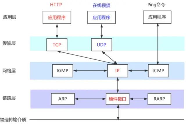
The names of some other protocols are explained in the figure above: ICMP (Internet Control Message Protocol) IGMP (Internet Group Management Protocol) ARP (Address Resolution Protocol) RARP (Reverse Address Resolution Protocol)
Detailed Characteristics of TCP Protocol
TCP is a transport layer protocol corresponding to the fourth layer of the OSI network model, with the following characteristics:
-
The TCP protocol is connection-based, meaning that a connection must be established before data can be transmitted.
-
Once a TCP connection is established, bidirectional communication can occur on that connection.
-
TCP transmission is based on byte streams rather than packets, numbering the data by byte size. The receiving end confirms the received data numbers through ACK. Through this mechanism, the TCP protocol can ensure the order and integrity of received data, thus providing reliable transmission.
-
TCP can also provide flow control capabilities by adjusting the sending rate of data through a sliding window. The essence of the sliding window is a dynamic buffer. The receiving end dynamically adjusts the window size in the TCP header according to its processing capacity and notifies the sending end through ACK acknowledgment packets, allowing the sending end to adjust the sending speed based on the window size.
-
Having flow control capability alone is not enough; the TCP protocol also considers that network issues may lead to a large number of retransmissions, further worsening the network situation. Therefore, the TCP protocol also provides congestion control. TCP handles congestion control mainly using four algorithms: slow start, congestion avoidance, congestion occurrence, and fast recovery.
Sequence Number and Acknowledgment Number
-
Sequence Number seq: Used to identify the byte stream sent from the TCP source to the destination. The sender marks this when sending data.
-
Acknowledgment Number ACK: At the receiving end, it is used to notify the sender that the data has been successfully received; its value equals the sender’s sequence number + 1 (i.e., the next sequence number expected by the receiver);
-
Flags: (A) SYN: Create a connection (B) ACK: Confirm the validity of the sequence number (C) FIN: Terminate a connection (D) RST: Reset the connection. (E) PSH: The receiving end should deliver this message to the application layer as soon as possible. (F) URG: Urgent pointer is valid.
TCP Three-Way Handshake
TCP is connection-based, so a connection must be established before data can be transmitted. TCP supports duplex transmission and does not distinguish between the Client and Server sides. For ease of understanding, we refer to the side initiating the connection request as the Client side, and the side passively establishing the connection as the Server side.
As shown in the figure below, the connection establishment sequence is from top to bottom, with the left and right sides representing the connection states of the Client and Server sides, respectively.
TCP provides connection-oriented communication transmission. Connection-oriented means that before data communication begins, preparations must be made between the two ends.
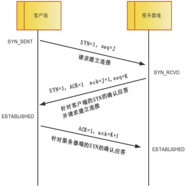
The so-called three-way handshake refers to the process of establishing a TCP connection, where the client and server need to send a total of three packets to confirm the establishment of the connection. In socket programming, this process is triggered by the client executing connect.
First Handshake: The client sets the SYN flag to 1, randomly generates a value seq=J, and sends this packet to the server, entering the SYN_SENT state while waiting for the server’s confirmation.
Second Handshake: After the server receives the packet, it knows that the client requests to establish a connection by the SYN=1 flag. The server sets both the SYN and ACK flags to 1, ack=J+1, randomly generates a value seq=K, and sends this packet back to the client to confirm the connection request, entering the SYN_RCVD state.
Third Handshake: The client receives the confirmation, checks whether ack is J+1 and ACK is 1. If correct, it sets the ACK flag to 1, ack=K+1, and sends this packet to the server. The server checks whether ack is K+1 and ACK is 1. If correct, the connection is successfully established, and both the client and server enter the ESTABLISHED state, completing the three-way handshake, after which data transmission between the client and server can begin.
Why Does TCP Handshake Require Three Steps?
TCP is a reliable transport control protocol, and the three-way handshake is the minimum number of steps required to ensure reliable data transmission while improving transmission efficiency.
Reason: To achieve reliable data transmission, both parties in the TCP protocol must maintain a sequence number to identify which packets have been received by the other party.
For example: When the sender sends a data packet (assuming a size of 10 bytes), it also sends a sequence number (assumed to be 500). When the receiver receives this data packet, it can reply with an acknowledgment number (510 = 500 + 10) to inform the sender, “I have received your data packet; you can send the next data packet starting from sequence number 511.”
The three-way handshake process is a necessary step for both parties in the communication to mutually inform the initial sequence number and confirm that the other party has received the initial sequence number.
If there were only two handshakes, at most only the initial sequence number of the connection initiator would be confirmed, and the sequence number chosen by the other party would not be confirmed.
As for why not four handshakes, it is clear that after three handshakes, both parties in the communication already know each other’s initial sequence numbers and have confirmed that each party knows the other’s initial sequence number, making a fourth handshake unnecessary.
Vulnerability of TCP’s Three-Way Handshake – SYN Flood Attack
There is a flaw in the TCP three-way handshake, which can be exploited for attacks. This attack is called SYN Flood Attack. In the second handshake of the three-way handshake, the server responds to the client’s request, and this response requires the client’s IP. The attacker forges this IP and continuously sends the content of the first handshake to the server, of course, with the forged client IP address, causing the server to be busy with the second handshake, but there is no result for the second handshake, which leads to the server being overwhelmed and crashing.
To counter such attacks, there are several solutions, the best being firewalls. Invalid Connection Monitoring Release continuously monitors all connections, including those with three-way handshakes and those with one handshake, regardless of whether they are normal or attacks. When a certain threshold is reached, these connections are terminated to release system resources. This method treats all connections equally, regardless of whether they are normal or attacks, so it is not recommended. Delayed TCB Allocation Method generally, after completing the first handshake, the server needs to allocate a TCB (Transmission Control Block) for that request, which usually requires over 200 bytes of resources. Delaying TCB allocation until a normal connection is established can effectively reduce the consumption of server resources.
Using Firewalls: Firewalls initiate SYN requests to internal servers (listeners) only after confirming the validity of the connection.
Detailed Explanation of Four-Way Teardown
The teardown of TCP connections is shown in the figure below.
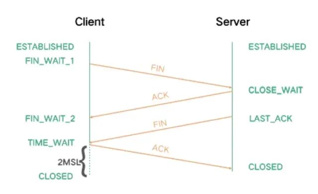
Both parties can initiate the closure of a TCP connection. For the sake of convenience, let’s assume that the side that initiates the closure is the Client. From the figure, it can be seen that both the Client and Server sides are in the ESTABLISHED state during communication, and then the Client actively initiates a closure request, sending a FIN packet to the Server, indicating that the Client has no more data to send, and then the Client enters the FIN_WAIT_1 state.
After receiving the FIN, the Server sends back an ACK and enters the CLOSE_WAIT state. At this point, the Server is in a half-closed state, as the Client will no longer send data to the Server, but the Server may still have data to send to the Client.
Once the Server completes sending its data, it will send a FIN to the Client, indicating that the Server also has no more data to send. At this point, the Server enters the LAST_ACK state and waits for the Client’s response to close the connection.
After the Client receives the Server’s FIN, it replies with an ACK and then enters the TIME_WAIT state. In the TIME_WAIT state, it needs to wait for twice the maximum segment lifetime to ensure reliable closure of the connection, and only then will it enter the CLOSED state. The Server, on the other hand, directly enters the CLOSED state after receiving the ACK.
Why do we need to wait for twice the maximum segment lifetime before closing the connection? There are two reasons:
-
To ensure that the TCP protocol’s full-duplex connection can be reliably closed;
-
To ensure that any duplicate data segments from this connection disappear from the network, preventing data confusion when the port is reused.
This interaction process shows that both connection establishment and teardown require actions in both directions. However, during connection establishment, the SYN and ACK from the Server side are combined into one send, while during teardown, the timing of data sending in both directions may differ, so FIN and ACK cannot be combined for sending. This is the reason for three-way handshakes during connection establishment and four-way teardowns.
Additionally, when addressing the teardown issue, it can be mentioned that in practical applications, one may encounter many sockets in TIME_WAIT or CLOSE_WAIT states. Generally, enabling tcp_tw_reuse and tcp_tw_recycle can speed up the recovery of TIME_WAIT sockets; while a large number of CLOSE_WAIT states may be due to bugs in the code of the passive closure side that do not correctly close the connection.
-
Why Wait for 2MSL: When the Client sends the fourth handshake packet, if the Server does not receive it, it will resend a FIN=1 packet. At this point, the Client is still in the TIME_WAIT state, so it can send a confirmation message again.
If there are many connections, and each time during connection and closure, three-way handshakes and four-way teardowns must be experienced, it is clear that this will lead to poor performance. Therefore, HTTP has a mechanism called keepalive connections, which can maintain the connection even after data transmission, allowing the client to use the recently freed connection directly when it needs to retrieve data again without needing to handshake again.
-
Why Three Handshakes and Two Confirmations?: Why does the client need to send a confirmation again? This is mainly to prevent invalid link request packets from suddenly reaching the server, causing errors. For example: If the client sends a connection request, but due to network or other factors, it does not reach the server within a certain time, the client does not receive confirmation. Because the client will resend the connection request, the three-way handshake establishes a connection with the server, but if the previous request reaches the server, the server will mistakenly think the client has sent a new connection request again and will send a message to the client agreeing to establish a connection. However, the client has already established a connection and will discard this message, and the server will not receive a response and will not establish the connection.
-
Measures When Errors Occur in Three-Way Handshake?: In the first handshake, if A sends SYN and the transmission fails, neither A nor B will request resources, and the connection fails. If multiple SYN connection requests are sent within a certain time, A will only accept the last SYN’s SYN+ACK response, ignoring all other responses, and the extra resources allocated by B will be released.
In the second handshake, if B sends SYN+ACK and the transmission fails, A will not request resources, but B will allocate resources but will not receive A’s ACK, which will be released after a period of time. If B receives multiple SYN requests from A, it will respond with SYN+ACK to all, but A will only acknowledge the earliest SYN response and respond to the last handshake ACK.
In the third handshake, if the ACK transmission fails, B does not receive the ACK and releases resources, returning RST (reset connection) for A’s subsequent data transmission. In fact, B will repeatedly send SYN+ACK because it did not receive A’s ACK, and the number of times can be set. If A’s ACK is still not received after multiple attempts, resources will be released, and B will return RST for A’s data transmission.