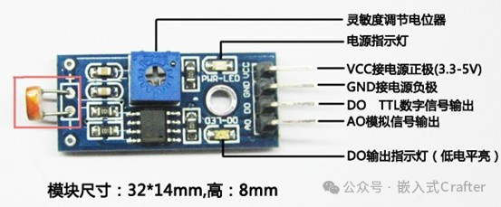
1.Hardware Introduction
The photoresistor is a special resistor made from semiconductor materials such as sulfide or selenide, and its working principle is based on the internal photoelectric effect.
As the light intensity increases, the resistance value rapidly decreases. The charge carriers generated by the light participate in conduction and drift under the influence of an external electric field, with electrons moving towards the positive terminal of the power supply and holes moving towards the negative terminal, resulting in a rapid decrease in the resistance of the photoresistor. In the absence of light, it is almost in a high-resistance state, exhibiting a large dark resistance.
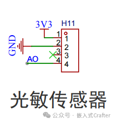
The analog output (AO) can be connected to the AD module, and through AD conversion, the value of environmental light intensity can be obtained.
2. Introduction to ADC
ADC, short for Analog-to-Digital Converter, is an electronic device that converts analog signals into digital signals, and it has a wide range of applications in electronic systems.
Working Principle
Analog signals are continuous signals that change over time, such as sound, temperature, and pressure in our daily lives. The electrical signals (like voltage or current) obtained from sensors that convert these physical quantities are analog signals.
Digital signals, on the other hand, are discrete and consist of 0s and 1s.The role of the ADC is to convert the continuously varying analog signals into discrete digital signals.
Its working process generally consists of four steps: sampling, holding, quantizing, and encoding:
Sampling: Taking values of the analog signal at regular time intervals, converting the time-continuous analog signal into a time-discrete sampled signal. For example, sampling an analog voltage signal 1000 times per second results in 1000 discrete voltage values.
Holding: Capturing the value of the analog signal at the moment of sampling and holding this value for a period of time, allowing the subsequent quantization and encoding processes to stably process this value.
Quantizing: Dividing the amplitude of the signal obtained after holding into discrete levels with a certain precision, approximating it to one of a finite number of discrete values. For example, dividing the voltage range of 0 – 5V into 256 levels, with each level corresponding to a quantized value.
Encoding: Representing the quantized result in binary code to form a digital signal. For instance, if the quantized value corresponds to the 100th level, the encoded result might be the binary 01100100.
Main Performance Indicators
Resolution: Refers to the smallest change in the analog quantity that the ADC can distinguish, usually expressed in terms of the number of bits of the converted digital signal.
For example, an 8-bit ADC can divide the input analog quantity into 2^8 = 256 levels, while a 12-bit ADC can divide it into 2^12 = 4096 levels. The higher the number of bits, the higher the resolution, allowing for smaller detectable changes in the analog quantity.
Conversion Accuracy: Indicates the deviation between the actual digital output of the ADC and the theoretical value, usually described in terms of error, such as absolute error or relative error.
Conversion Speed: Refers to the time required to complete the conversion from an analog signal to a digital signal, typically measured in seconds (s), milliseconds (ms), or microseconds (μs). Different application scenarios have different requirements for conversion speed; for instance, audio processing may require a faster conversion speed.
3. Software Design
The AO pin is connected to PB0 of the STM32, corresponding to ADC1_IN8.
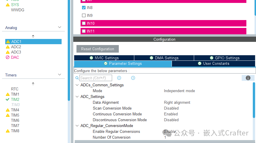
3.1.STM32CubeMX Configuration
The parameters are set to default, independent mode, data right-aligned, and continuous conversion mode.
/* USER CODE BEGIN Header *//** ****************************************************************************** * @file adc.c * @brief This file provides code for the configuration * of the ADC instances. ****************************************************************************** * @attention * * Copyright (c) 2024 STMicroelectronics. * All rights reserved. * * This software is licensed under terms that can be found in the LICENSE file * in the root directory of this software component. * If no LICENSE file comes with this software, it is provided AS-IS. * ****************************************************************************** *//* USER CODE END Header *//* Includes ------------------------------------------------------------------*/#include "adc.h"/* USER CODE BEGIN 0 *//* USER CODE END 0 */ADC_HandleTypeDef hadc1;/* ADC1 init function */void MX_ADC1_Init(void){ /* USER CODE BEGIN ADC1_Init 0 */ /* USER CODE END ADC1_Init 0 */ ADC_ChannelConfTypeDef sConfig = {0}; /* USER CODE BEGIN ADC1_Init 1 */ /* USER CODE END ADC1_Init 1 */ /** Common config */ hadc1.Instance = ADC1; hadc1.Init.ScanConvMode = ADC_SCAN_DISABLE; hadc1.Init.ContinuousConvMode = ENABLE; hadc1.Init.DiscontinuousConvMode = DISABLE; hadc1.Init.ExternalTrigConv = ADC_SOFTWARE_START; hadc1.Init.DataAlign = ADC_DATAALIGN_RIGHT; hadc1.Init.NbrOfConversion = 1; if (HAL_ADC_Init(&hadc1) != HAL_OK) { Error_Handler(); } /** Configure Regular Channel */ sConfig.Channel = ADC_CHANNEL_8; sConfig.Rank = ADC_REGULAR_RANK_1; sConfig.SamplingTime = ADC_SAMPLETIME_1CYCLE_5; if (HAL_ADC_ConfigChannel(&hadc1, &sConfig) != HAL_OK) { Error_Handler(); } /* USER CODE BEGIN ADC1_Init 2 */ /* USER CODE END ADC1_Init 2 */}void HAL_ADC_MspInit(ADC_HandleTypeDef* adcHandle){ GPIO_InitTypeDef GPIO_InitStruct = {0}; if(adcHandle->Instance==ADC1) { /* USER CODE BEGIN ADC1_MspInit 0 */ /* USER CODE END ADC1_MspInit 0 */ /* ADC1 clock enable */ __HAL_RCC_ADC1_CLK_ENABLE(); __HAL_RCC_GPIOB_CLK_ENABLE(); /**ADC1 GPIO Configuration PB0 ------> ADC1_IN8 */ GPIO_InitStruct.Pin = GPIO_PIN_0; GPIO_InitStruct.Mode = GPIO_MODE_ANALOG; HAL_GPIO_Init(GPIOB, &GPIO_InitStruct); /* ADC1 interrupt Init */ HAL_NVIC_SetPriority(ADC1_2_IRQn, 7, 0); HAL_NVIC_EnableIRQ(ADC1_2_IRQn); /* USER CODE BEGIN ADC1_MspInit 1 */ /* USER CODE END ADC1_MspInit 1 */ }}void HAL_ADC_MspDeInit(ADC_HandleTypeDef* adcHandle){ if(adcHandle->Instance==ADC1) { /* USER CODE BEGIN ADC1_MspDeInit 0 */ /* USER CODE END ADC1_MspDeInit 0 */ /* Peripheral clock disable */ __HAL_RCC_ADC1_CLK_DISABLE(); /**ADC1 GPIO Configuration PB0 ------> ADC1_IN8 */ HAL_GPIO_DeInit(GPIOB, GPIO_PIN_0); /* ADC1 interrupt Deinit */ HAL_NVIC_DisableIRQ(ADC1_2_IRQn); /* USER CODE BEGIN ADC1_MspDeInit 1 */ /* USER CODE END ADC1_MspDeInit 1 */ }}/* USER CODE BEGIN 1 *//* USER CODE END 1 */3.2. Photoresistor Sensor Code
#include "adc_light.h"extern ADC_HandleTypeDef hadc1;float Get_Light_Value(void){ float Light_Value; uint16_t ADC_Value, i; HAL_ADC_Start(&hadc1); HAL_ADC_PollForConversion(&hadc1, 10); for(i=0; i<30; i++) ADC_Value += HAL_ADC_GetValue(&hadc1); HAL_ADC_Stop(&hadc1); ADC_Value = ADC_Value / 30; Light_Value = ADC_Value * 330/4096;//Data conversion, voltage is 3.3V, data is 12 bits, keep two decimal places printf("LightADC: %d, LightValue: %.2f\r\n",ADC_Value, Light_Value); return Light_Value;}