1. Rectangular Wave
1.1 Parameters
The rectangular wave is a periodic waveform that switches between two fixed levels, as shown in the figure below.
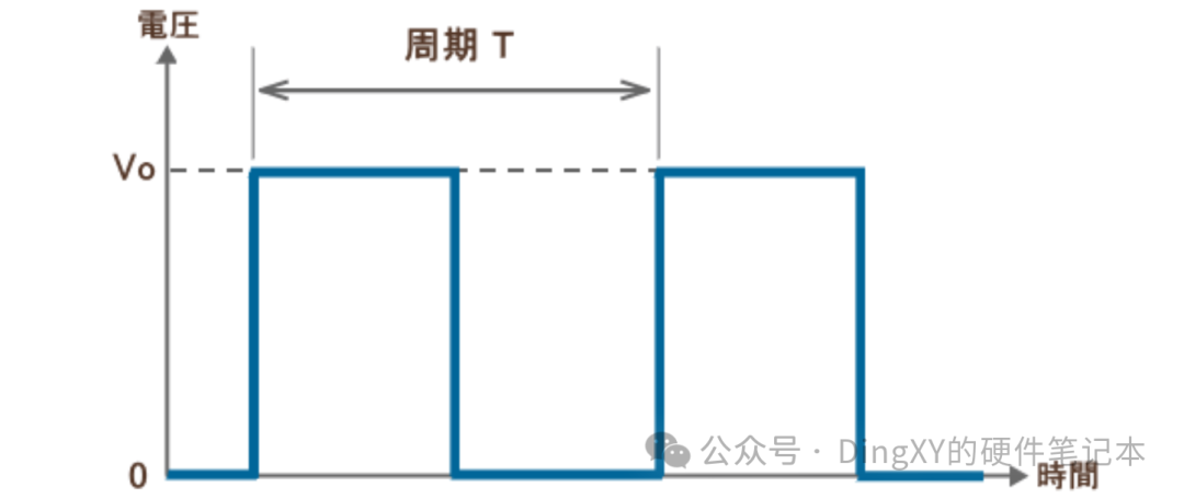
(1) Period T (seconds), frequency f = 1/T (Hz).
(2) Duty cycle D: the ratio of the duration of the high level to the period, 0 ≤ d ≤ 1 (usually expressed in %).
(3) High level amplitude A, the level corresponding to the high level; the low level can be 0, -A, or other values (depending on the specific definition).
1.2 Time Domain Representation
Let the high level be A, the low level be B, and the high level lasts for dT, then the expression is: x(t) = { A, 0 ≤ t < dT ; B, dT ≤ t < T }, and it repeats with period T.
1.3 DC Component (Average Value) and Effective Value (RMS)
(1) Average value: X_avg = A·d + B·(1−d)
(2) Root Mean Square: X_rms = sqrt(d·A·A + (1−d)·B·B)
2. Verilog Code
2.1 Function Description
(1) A rectangular wave with adjustable frequency and duty cycle parameters.
(2) Frequency and duty cycle data need to be input from external sources one clock cycle in advance.
(3) Control instructions
IDLE = 2’d0 ;// Idle
INT = 2’d1 ;// Interrupt
START = 2’d2 ;// Start
2.2 Source Code
See the code on CSDN account https://blog.csdn.net/sinat_36503471?type=blog2.3 TestBench Simulation Code
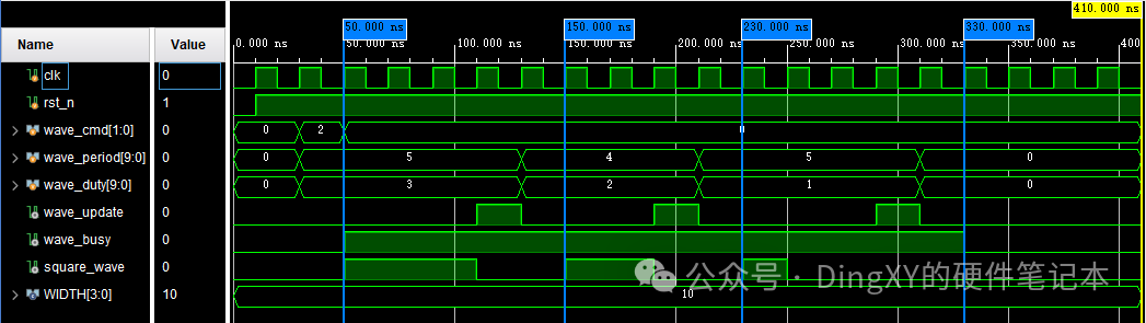
See the code on CSDN account https://blog.csdn.net/sinat_36503471?type=blog2.4 Simulation Results