This article mainly introduces the design principles of digital multimeters and the calculation methods for average value and true RMS value, explaining the defects of the average value calculation method and the calculation method for true RMS value of AC signals superimposed with DC signals. It emphasizes the necessity of using multimeters with true RMS calculation methods.
Keywords: Multimeter, Conversion Circuit, Average Value, True RMS, AC+DC
A multimeter, also known as a multifunction meter, is an indispensable measuring instrument in power electronics and other fields, primarily used to measure voltage, current, and resistance. Multimeters are classified based on their display methods into analog multimeters and digital multimeters, with digital multimeters being the most commonly used today. The following introduces the circuit design principles and measurement calculation methods of digital multimeters.1. Circuit Design Principles The measurement process of a digital multimeter involves a conversion circuit that converts the measured value into a DC voltage signal, which is then converted from analog to digital by an A/D converter. The electronic counter counts the voltage, and the measurement result is displayed directly on the screen. This process can be represented in Figure 1.1.
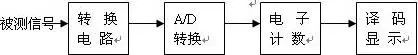
Figure 1.1 Measurement Process of Multimeter
The functions of measuring voltage, current, and resistance with a multimeter are realized through the conversion circuit, and the measurement of current and resistance is based on voltage measurement. In other words, the digital multimeter is an extension of the digital DC voltmeter. Below is an introduction to the main conversion circuits of a DC voltmeter.1.1 Principle of DC Voltage Measurement: First, let’s understand the composition and working principle of a digital DC voltmeter (see Figure 1.2).
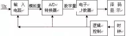
Figure 1.2 Composition of Digital DC Voltmeter
The A/D converter of the digital DC voltmeter converts the continuously varying analog voltage into a digital quantity, which is then counted by the electronic counter to obtain the measurement result, which is displayed by the decoding display circuit. The logic control circuit coordinates the work of the circuit, completing the entire measurement process in sequence under the action of the clock. Depending on the A/D conversion method used, it can be divided into integrating and non-integrating types. The working principle of a DC voltmeter will be introduced using the dual-slope integrating method as an example. The structure of the DC voltmeter is shown in Figure 1.3, and the working waveform is shown in Figure 1.4.
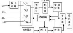
Figure 1.3 Composition of Dual-Slope DC Voltmeter
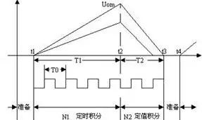
Figure 1.4 Working Waveform of Dual-Slope DC Voltmeter
In Figure 1.3, Ux is the measured voltage, and Un is the reference voltage, with the logic control circuit controlling the measurement sequence. A single measurement of the dual-slope DC voltmeter includes the following three stages: (Please contact Beijing Ocean Xingye Technology Co., Ltd. at (Phone: 62178811/62176106))
(1) Preparation Stage (t0—t1): The control circuit closes the switch S4 in the controllable switch while the others are disconnected, making the integrator output U0 =0.
(2) Sampling Stage (t1—t2): Assuming the measured voltage Ux is negative. At t=t1, S4 is disconnected and S1 is closed, allowing the integrator to integrate Ux, causing U0 to rise linearly from zero, while the gate is opened, and the counter’s counting capacity is N1. When the counter’s value reaches N1+1, this moment is recorded as t2, and the counter overflows, producing a carry pulse to the logic control circuit, which then disconnects switch S1. At t=t2:

N1, T0, R, and C are constant values, and U0 is determined by the measured voltage Ux.
(3) Comparison Stage (t2—t3): At t=t2, the logic control circuit opens the gate, resets the counter to zero, and starts counting again, while simultaneously disconnecting switch S1 and closing S2, allowing the integrator to perform reverse integration on Un. The output U0 of the integrator linearly decreases from Uom to zero, and this moment is recorded as t3. At t1:
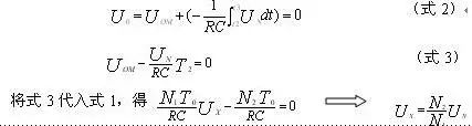
If we take Un=N1, then Ux=N2. At the moment t3, the zero comparator input signal is sent to the logic control circuit, causing the logic control circuit to close the gate, stop counting, and control the register to send the counting result to the decoding display circuit, which displays the measurement result directly as number N2.
1.2 Current – Voltage Conversion Circuit
The circuit diagram of the current-voltage converter is shown in Figure 1.5. When the 20mA range is selected, the voltage between points A and B in the figure is close to 200mV, and the resistance connected to the multimeter is 0.99+0.1=1Ω. According to Ohm’s Law, I=U/R.
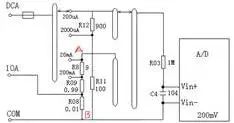
Figure 1.5 Current – Voltage Conversion Circuit
1.3 Resistance – Voltage Conversion Circuit
The resistance-voltage conversion circuit is shown in Figure 1.6. In the figure, I is the test current inside the DC voltmeter, which creates a voltage drop across Rx proportional to the measured resistance Rx. By measuring this voltage drop, we can determine the value of the measured resistance Rx, where Rx=U/I.
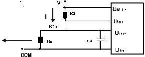
Figure 1.6 Resistance – Voltage Conversion Circuit
1.4 AC – DC Conversion Circuit:
As shown in Figure 1.7, the measurement of AC voltage uses average value response and effective value display. Similar to DC voltage, it first passes through a voltage divider, then is half-wave rectified and restored to DC, and finally undergoes A/D conversion.
2. Measurement Calculation Methods of Multimeters
When using a multimeter to measure AC voltage or current, have you ever doubted the measurement results? When you are confident in your circuit, you might question the accuracy of the multimeter measurements. So where could the problem lie? Let’s review the mathematical calculation formulas for measuring AC signals with a multimeter. 1. Differences Between Average Value and True RMS Measurement:
First, let’s understand the average value, which mathematically is expressed as:
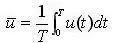
Where u(t) is the function expression of the signal, and T is the period of the signal. If we are measuring a standard sine wave, this calculation method is accurate and quick. However, when measuring other AC signals (such as a square wave):
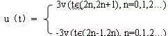 Using equation 4 to calculate the average value of the above signal, assuming the period of the above signal is 2, we get:
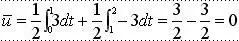 The result is evidently incorrect. Therefore, we conclude that using the average value method to calculate AC signals such as square waves and sawtooth waves can lead to significant errors. So, is there a method to accurately measure non-sinusoidal AC signals? Hence, the calculation method for true RMS value was introduced. True RMS is the root mean square of current or voltage over a period, and its mathematical calculation formula is as follows:
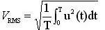
Where Vrms represents the true RMS value of the voltage, u(t) is the function expression of the signal, and T is the period of the signal. Using the above formula, we first integrate the square of the signal, then take the square root. This method accurately calculates the effective value of various AC signals. Therefore, using the true RMS calculation method to measure AC signals is accurate. When selecting a multimeter, it is essential to choose one with true RMS measurement capabilities.
2. True RMS of AC+DC Derived from True RMS Function:
In various measured signals, there are often AC signals superimposed with DC signals. Previously, the multimeters we used could only measure DC or AC signals separately, and could not measure the superimposed signals of DC and AC. So how do we accurately measure the superimposed AC and DC signals?
First, it is important to understand that the superimposed AC and DC signals are not simply the sum of the true RMS of the AC signal and the magnitude of the DC signal. For example, let’s take a DC signal u1(t)=1(v) and an AC signal u2(t)=sint. After superimposing, the signal is represented as: u(t)=1+2sint; the true RMS value of this signal is u(t)=1.732, not 1+1.414=2.414. Substituting the superimposed DC and AC signals into the true RMS calculation formula yields:
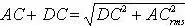 Where AC+DC represents the true RMS value of the superimposed signal, DC represents the magnitude of the DC signal, and ACrms represents the true RMS value of the AC signal. This allows for accurate calculation of the superimposed AC and DC signals. The AC+DC function is significant for testing peak power. Distortion and harmonics from DC superimposition can cause transformers, generators, and motors to overheat, as well as lead to circuit breakers tripping and fuses blowing. This should not be overlooked during measurements, thus it is necessary to choose a multimeter with AC+DC true RMS measurement capabilities (e.g., OI859CF handheld multimeter).
In summary, the multimeter achieves the measurement of AC voltage, current, and resistance based on the DC voltmeter through circuit conversion. Using the true RMS calculation method to measure non-sinusoidal AC signals is more accurate, which will aid us in better research and experimentation.