
Sharing is not limited to smart embedded information
『Smart Embedded Apprentice Group
『Smart Embedded Apprentice Group
With the arrival of the AIoT (Artificial Intelligence of Things) era, embedded systems are undergoing a revolution. From low-spec hardware to high-performance chips, from simple logic to complex business logic, the demand for embedded systems is growing increasingly. Today, we will learn about the software frameworks for embedded devices in the AIoT era, and how design patterns can facilitate this transformation.
Evolution of Embedded Systems
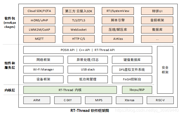
Embedded systems were once known for their resource constraints and simple code. However, in the AIoT era, improvements in chip performance and the complexity of business logic have raised higher demands for code reusability and portability. This not only shortens project cycles but also enhances maintainability. Below are common software frameworks for embedded devices in the AIoT era:
Design Patterns: Advanced Language for Embedded Systems
How do design patterns play a role in the world of embedded C programming?
Design patterns are characterized by<span> advanced language</span>, <span> high-end</span>, and <span> architecture</span>, and can be described as: for a certain type of similar problems, through continuous attempts by predecessors, recognized effective solutions for handling such problems have been summarized.
Design patterns, such as <span>Observer Pattern</span> and <span>Chain of Responsibility Pattern</span>, provide recognized effective methods for solving specific problems. They are independent of the programming language and are strategies for problem-solving, equally important for C language programmers.
Observer Pattern: The Guardian of State Changes
The Observer Pattern allows for a one-to-many dependency between objects, so that when the state of one object changes, all its dependents are notified. In embedded systems, this can be used to implement a low-power framework, managing device power states through registration and notification mechanisms.
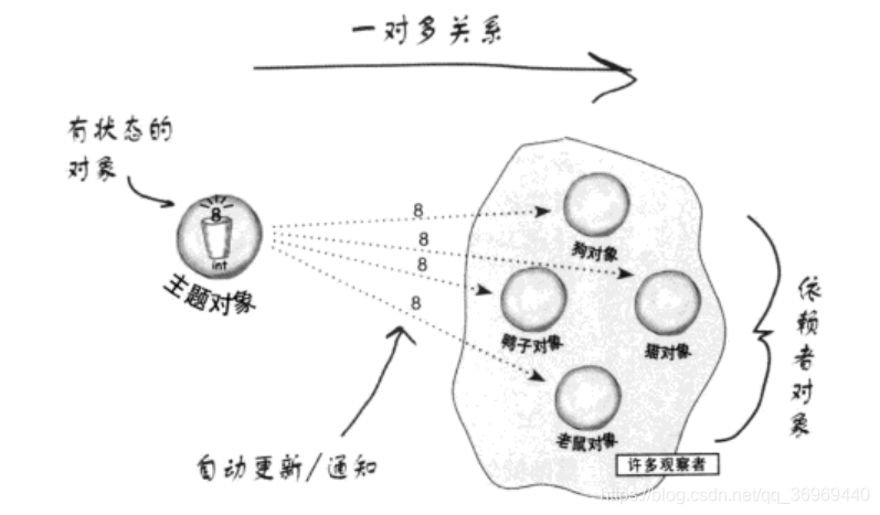
By using the Observer Pattern, we can build a <span>PM</span> (Power Management) framework that allows devices to enter low-power mode when certain conditions are met.
-
Implementation
The subject object provides a unified registration interface and registration function. The observer itself instantiates the <span>observer_intf</span> interface and then uses the registration function to add it to the corresponding subject list. When the subject’s state changes, it notifies all objects in the list sequentially.
struct observer_ops
{
    void*(handle)(uint8_t evt);
};

struct observer_intf
{
    struct observer_intf* next;
    const char* name;
    void* condition;
    const struct observer_ops *ops;
}

int observer_register(struct topical* top , struct observer_intf* observer);
When the subject’s state changes, notifications will be sent to all observers, who can also set conditions to choose whether to receive notifications.
struct observer_intf observer_list;

void XXXX_topical_evt(uint8_t evt)
 {
      struct observer_intf* cur_observer = observer_list.next;
      uint8_t* condition = NULL;
      while(cur_observer != NULL)
      {
          condition = (uint8_t*)cur_observer->condition;
          if(NULL == condition || (condition && *condition))
          {
              if(cur_observer->ops->handle){
                  cur_observer->ops->handle(evt);
              }
          }
          cur_observer = cur_observer->next;
      }
 }
-
Example: Embedded Bare Metal Low Power Framework
-
Device Power Consumption Distribution
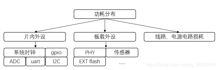
Among them, line losses, power circuits, etc. cannot be controlled by software, so they are not discussed. Onboard peripherals, such as sensors, may be configured to enter low-power mode through a certain command, or hardware may support controlling peripheral power to manage power consumption. Internal and external chip peripherals can control power consumption by unloading related drivers and shutting down clock configuration working modes.
-
Device Wake-up Methods
Active Wake-up: The system is actively woken up to handle events when a certain timing event occurs;
Passive Wake-up: The system is in sleep mode, woken up by external events, such as when the serial port receives a data packet or when a sensor detects a change, notifying the chip through pins;
Conditions for allowing the system to sleep: No data is being transmitted or received by the peripherals; no data needs to be processed in the cache; the application layer status is idle (no events to process);
Implementation of PM framework based on Observer Pattern:
// PM component provided interface
struct pm
{
    struct pm* next;
    constchar* name;
    void(*init)(void);
    void(*deinit(void);
    void* condition;
};
static struct pm pm_list;
staticuint8_t pm_num;
staticuint8_t pm_status;

int pm_register(const struct pm* pm , constchar* name)
{
     struct pm* cur_pm =  &pm_list;
     while(cur_pm->next)
     {
         cur_pm = cur_pm->next;
     }
     cur_pm->next = pm;
     pm->next = NULL;
     pm->name = name;
     pm_num++;
}

void pm_loop(void)
{
    uint32_t pm_condition = 0;
    struct pm* cur_pm =  pm_list.next;
    staticuint8_t cnt;

    /*check all condition*/
    while(cur_pm)
    {
        if(cur_pm->condition){
         pm_condition |=  *((uint32_t*)(cur_pm->condition));
        }
        cur_pm = cur_pm->next;
    }
    if(pm_condition == 0)
    {
      cnt++;
        if(cnt>=5)
        {
            pm_status = READY_SLEEP;
        }
    }
    else
    {
        cnt = 0;
    }
    if( pm_status == READY_SLEEP)
    {
         cur_pm =  pm_list.next;
         while(cur_pm)
         {
             if(cur_pm->deinit){
                cur_pm->deinit();
             }
             cur_pm = cur_pm->next;
         }
        pm_status = SLEEP;
        ENTER_SLEEP_MODE();
    }
    /*sleep--->wakeup*/
    if(pm_status == SLEEP)
    {
         pm_status = NORMAL;
         cur_pm =  pm_list.next;
         while(cur_pm)
         {
             if(cur_pm->init){
                cur_pm->init();
             }
             cur_pm = cur_pm->next;
         }
    }
}
// Peripheral using PM interface
struct uart_dev
{
    ...
    struct pm pm;
    uint32_t pm_condition;
};
struct uart_dev uart1;

void hal_uart1_init(void);
void hal_uart1_deinit(void);

void uart_init(void)
{
    uart1.pm.init =  hal_uart1_init;
    uart1.pm.deinit =  hal_uart1_deinit;
    uart1.pm.condition = &uart1.pm_condition;
    pm_register(&uart1.pm , "uart1");
}
/*Next, the serial driver checks whether the cache, send, and receive are idle or busy, and assigns a value to uart1.pm_condition*/
-
Conclusion
-
PM power management can form a module on its own, and when the number of power-consuming peripherals increases, it only needs to implement the interface and register;
-
By defining segments to export operations, the registration logic of the application layer or peripherals can be further simplified;
-
It is convenient for debugging, allowing easy printing of the modules that currently do not meet sleep conditions;
-
By dividing based on conditional fields, it should be possible to achieve partial sleep of the system.
Chain of Responsibility Pattern: The Conductor of Sequential Logic
The Chain of Responsibility Pattern is suitable for scenarios where a series of tasks need to be processed in strict chronological order. In embedded systems, this can be used to implement sequential logic for configuring modules like WiFi, ensuring tasks are executed in the correct order.
The Chain of Responsibility Pattern can also be used to implement complex task sequences, such as network configuration, ensuring each step is executed in order.
-
Scenario
In real life, many tasks require multiple objects to collaborate. For example, in a company reimbursement process, employees must organize accurate reimbursement forms and submit them to the finance department, which verifies and decides approval authority based on the amount, with large amounts requiring the general manager’s approval. Similarly, when configuring a WiFi module, AT commands need to be sent in sequence, and the next command’s execution depends on the return result of the previous command.
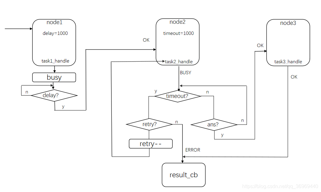
In summary, a series of tasks need to be processed in strict chronological order, as shown in the figure below:
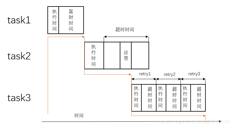
In the presence of a system, such logic can easily be implemented using blocking delays, as follows:
void process_task(void)
{
task1_process();
msleep(1000);
task2_process();
mq_recv(¶m , 1000);
task3_process();
while(mq_recv(¶m , 1000) != OK)
{
if(retry)
{
task3_process();
--try;
}
}
}
In a bare-metal situation, to ensure the system’s real-time performance, blocking delays cannot be used; generally, timed events combined with state machines are used to achieve:
void process_task(void)
{
     switch(task_state)
     {
         case task1:
             task1_process();
             set_timeout(1000);break;
         case task2:
             task1_process();
             set_timeout(1000);break;
         case task3:
             task1_process();
             set_timeout(1000)break;
         default:break;
     }
}

/*Timer timeout callback*/
void timeout_cb(void)
{
    if(task_state == task1)
    {
        task_state = task2;
        process_task();
    }
    else//task2 and task3
    {
        if(retry)
        {
            retry--;
             process_task();
        }
    }
}

/*Task response callback*/
void task_ans_cb(void* param)
{
    if(task==task2)
    {
        task_state = task3;
        process_task();
    }
}
Compared to system implementation, bare-metal implementation is more complex; to avoid blocking, sequential delay logic can only be achieved through states and timers. As can be seen, the implementation process is quite dispersed, with the processing of a single task spread across three functions, leading to difficulties in modification and portability. In actual applications, similar logic is quite common, and implementing it as described above will result in strong coupling of the application.
-
Implementation
It can be observed that the above scenarios have the following characteristics:
-
Tasks are executed in order, and only when the current task is completed (with a conclusion, either success or failure) is the next task allowed to be executed;
-
The execution result of the previous task will affect the execution of the next task;
-
Tasks have certain properties, such as timeout, delay time, and retry count.
Based on the above information, we can abstract a model: the task model, treating tasks as nodes, with each node having attributes such as timeout, delay, retry, etc. Tasks are linked in sequence, starting execution from the first node, with results being OK, BUSY, or ERROR. OK indicates that the node has completed processing and is removed from the chain; ERROR stops the task chain and triggers an error callback; BUSY indicates that the task is waiting for a response or delay. When all nodes are completed, a success callback is performed, as shown in the figure below:
// Node data structure definition
typedefstruct shadow_resp_chain_node
{
    uint16_t timeout;
    uint16_t duration;
    uint8_t init_retry;
    uint8_t param_type;
    uint16_t retry;
    /*used in mpool*/
    struct shadow_resp_chain_node* mp_prev;
    struct shadow_resp_chain_node* mp_next;

    /*used resp_chain*/
    struct shadow_resp_chain_node* next;

    node_resp_handle_fp handle;
    void* param;
}shadow_resp_chain_node_t;
-
Node Memory Pool
The necessity of using a memory pool lies in the fact that, although the number of chains and the number of nodes in a single chain are limited, there are many types; for example, modules supporting AT commands may involve dozens of commands, while a single configuration operation usually only requires 3-5 commands. If all nodes are statically defined, it will waste a lot of memory resources, so dynamic allocation is necessary.
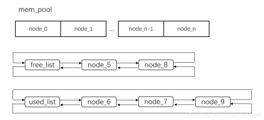
When initializing the node memory pool, all nodes are added to the free_list. When a node is requested, the first free node is taken out, added to the used_list, and connected to the responsibility chain. After the node execution is completed, it is automatically removed from the responsibility chain and used_list, then added back to the free_list, achieving efficient memory management.
// Responsibility chain data structure definition
typedefstruct resp_chain
{
    bool enable;               //enable == true Responsibility chain starts
    bool  is_ans;              //Received response, together with void* param forms the response signal

    uint8_t state;
    constchar* name;
    void* param;
    TimerEvent_t timer;
    bool timer_is_running;
    shadow_resp_chain_node_t node;        //Node chain
    void(*resp_done)(void* result);       //Execution result callback
}resp_chain_t;
// Responsibility chain initialization
void resp_chain_init(resp_chain_t* chain ,  const char* name ,
                                            void(*callback)(void* result))      {
    RESP_ASSERT(chain);
    /*only init one time*/
    resp_chain_mpool_init();

    chain->enable = false;
    chain->is_ans = false;
    chain->resp_done = callback;
    chain->name = name;

    chain->state = RESP_STATUS_IDLE;
    chain->node.next = NULL;
    chain->param = NULL;

    TimerInit(&chain->timer,NULL);
}
// Responsibility chain add node
int resp_chain_node_add(resp_chain_t* chain ,
                        node_resp_handle_fp handle , void* param)
{
    RESP_ASSERT(chain);
    BoardDisableIrq();
    shadow_resp_chain_node_t* node = chain_node_malloc();
    if(node == NULL)
    {
        BoardEnableIrq();
        RESP_LOG("node malloc error ,no free node");
        return-2;
    }
    /*Initialize node and add to responsibility chain*/
    shadow_resp_chain_node_t* l = &chain->node;
    while(l->next != NULL)
    {
        l = l->next;
    }
    l->next = node;
    node->next = NULL;
    node->handle = handle;
    node->param = param;
    node->timeout = RESP_CHIAN_NODE_DEFAULT_TIMEOUT;
    node->duration = RESP_CHIAN_NODE_DEFAULT_DURATION;
    node->init_retry = RESP_CHIAN_NODE_DEFAULT_RETRY;
    node->retry = (node->init_retry == 0)? 0 :(node->init_retry-1);
    BoardEnableIrq();
    return0;
}
// Responsibility chain start
void resp_chain_start(resp_chain_t* chain)
{
    RESP_ASSERT(chain);
    chain->enable = true;
}
// Responsibility chain response
void resp_chain_set_ans(resp_chain_t* chain , void* param)
{
    RESP_ASSERT(chain);
    if(chain->enable)
    {
        chain->is_ans = true;
        if(param != NULL)
            chain->param = param;
        else
        {
            chain->param = "NO PARAM";
        }
    }
}
// Responsibility chain run
int resp_chain_run(resp_chain_t* chain)
{
    RESP_ASSERT(chain);
    if(chain->enable)
    {
        shadow_resp_chain_node_t* cur_node = chain->node.next;
        /*maybe ans occur in handle,so cannot change state direct when ans comming*/
        if(chain->is_ans)
        {
            chain->is_ans = false;
            chain->state = RESP_STATUS_ANS;
        }

        switch(chain->state)
        {
            case RESP_STATUS_IDLE:
            {
                if(cur_node)
                {
                    uint16_t retry = cur_node->init_retry;
                    if(cur_node->handle)
                    {
                        cur_node->param_type = RESP_PARAM_INPUT;
                        chain->state = cur_node->handle((resp_chain_node_t*)cur_node,cur_node->param);
                    }
                    else
                    {
                        RESP_LOG("node handle is null ,goto next node");
                        chain->state = RESP_STATUS_OK;
                    }
                    if(retry != cur_node->init_retry)
                    {
                        cur_node->retry = cur_node->init_retry>0?(cur_node>init_retry-1):0;}
                }
                else
                {
                    if(chain->resp_done)
                    {
                        chain->resp_done((void*)RESP_RESULT_OK);
                    }
                    chain->enable = 0;
                    chain->state = RESP_STATUS_IDLE;
                    TimerStop(&chain->timer);
                    chain->timer_is_running  = false;
                }
                break;
            }
            case RESP_STATUS_DELAY:
            {
                if(chain->timer_is_running == false)
                {
                    chain->timer_is_running  = true;
                    TimerSetValueStart(&chain->timer , cur_node->duration);
                }
                if(TimerGetFlag(&chain->timer) == true)
                {
                    chain->state = RESP_STATUS_OK;
                    chain->timer_is_running  = false;
                }
                break;
            }
            case RESP_STATUS_BUSY:
            {
                /*waiting for ans or timeout*/
                if(chain->timer_is_running == false)
                {
                    chain->timer_is_running  = true;
                    TimerSetValueStart(&chain->timer , cur_node->timeout);
                }
                if(TimerGetFlag(&chain->timer) == true)
                {
                    chain->state = RESP_STATUS_TIMEOUT;
                    chain->timer_is_running  = false;
                }
                break;
            }
            case RESP_STATUS_ANS:
            {
                /*already got the ans,put the param back to the request handle*/
                TimerStop(&chain->timer);
                chain->timer_is_running  = false;
                if(cur_node->handle)
                {
                    cur_node->param_type = RESP_PARAM_ANS;
                    chain->state = cur_node->handle((resp_chain_node_t*)cur_node ,                                                                 chain->param);
                }
                else
                {
                    RESP_LOG("node handle is null ,goto next node");
                    chain->state = RESP_STATUS_OK;
                }
                break;
            }
            case RESP_STATUS_TIMEOUT:
            {
                if(cur_node->retry)
                {
                    cur_node->retry--;
                    /*retry to request until cnt is 0*/
                    chain->state = RESP_STATUS_IDLE;
                }
                else
                {
                    chain->state = RESP_STATUS_ERROR;
                }
                break;
            }
            case RESP_STATUS_ERROR:
            {
                if(chain->resp_done)
                {
                    chain->resp_done((void*)RESP_RESULT_ERROR);
                }
                chain->enable = 0;
                chain->state = RESP_STATUS_IDLE;
                TimerStop(&chain->timer);
                chain->timer_is_running  = false;
                cur_node->retry = cur_node->init_retry>0?(cur_node->init_retry-1):0;
                chain_node_free_all(chain);
                break;
            }
            case RESP_STATUS_OK:
            {
                /*get the next node*/
                cur_node->retry = cur_node->init_retry>0?(cur_node->init_retry-1):0;
                chain_node_free(cur_node);
                chain->node.next = chain->node.next->next;
                chain->state = RESP_STATUS_IDLE;
                break;
            }
            default:
            break;
            }
        }
    return chain->enable;
}
-
Test Cases
// Responsibility chain definition and initialization
void chain_test_init(void)
{
    resp_chain_init(&test_req_chain , "test request" , test_req_callback);
}

// Define run function, called in the main loop
void chain_test_run(void)
{
    resp_chain_run(&test_req_chain);
}

// Test node addition and start trigger function

void chain_test_tigger(void)
{
    resp_chain_node_add(&test_req_chain ,  node1_req ,NULL);
    resp_chain_node_add(&test_req_chain ,  node2_req,NULL);
    resp_chain_node_add(&test_req_chain ,  node3_req,NULL);
    resp_chain_start(&test_req_chain);
}

// Implement node request functions
/*Delay 1s before executing the next node*/
int node1_req(resp_chain_node_t* cfg, void* param)
{
    cfg->duration = 1000;
    RESP_LOG("node1 send direct request: delay :%d ms" , cfg->duration);
    return RESP_STATUS_DELAY;
}

/*Timeout 1S, retransmission 5 times*/
int node2_req(resp_chain_node_t* cfg , void* param)
{
    staticuint8_t cnt;
    if(param == NULL)
    {
        cfg->init_retry = 5;
        cfg->timeout  = 1000;

        RESP_LOG("node2 send request max retry:%d , waiting for ans...");
        return RESP_STATUS_BUSY;
    }
    RESP_LOG("node2 get ans: %d",(int)param);
    return RESP_STATUS_OK;
}

/*Non-asynchronous request*/
int node3_req(resp_chain_node_t* cfg , void* param)
{
    RESP_LOG("node4 send direct request");
    return RESP_STATUS_OK;
}

void ans_callback(void* param)
{
    resp_chain_set_ans(&test_req_chain , param);
}
Summary
The application of design patterns not only simplifies the development of embedded systems but also enhances the maintainability and portability of the code. With the arrival of the AIoT era, these patterns will become indispensable tools for embedded development.
Today’s sharing ends👇Follow to not get lost, continue tomorrow