This article is reprinted from the Jishu Community
Jishu Column: Arm Technology Blog
Source: https://zhuanlan.zhihu.com/p/52855259
In this article, we will discuss a very important concept in embedded systems – registers. Since microcontrollers interact with the external environment and control their own functions primarily through registers, the use of registers will be integral to the entire learning process of microcontrollers. This article will introduce the concept and operation of registers by hand-on rewriting our Blinky program.
The first half of the article will explain the basic principles of registers, while the second half will demonstrate how to operate registers through code examples.
The embedded platform used here is STM32F103, and its register manual can be downloaded here.
Registers refer to a special memory address area, but they do not correspond to actual SRAM (Static Random-Access Memory). Operations on registers are completely consistent with operations on memory; we can treat registers as memory for reading and writing, and reading and writing to the register memory segment will be converted to data exchange with peripherals on the bus.
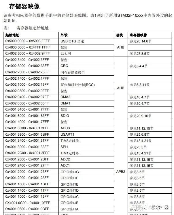
Therefore, operations on registers are essentially read and write operations on special address memory. In the manual, we can find the starting addresses of various registers (page 28):
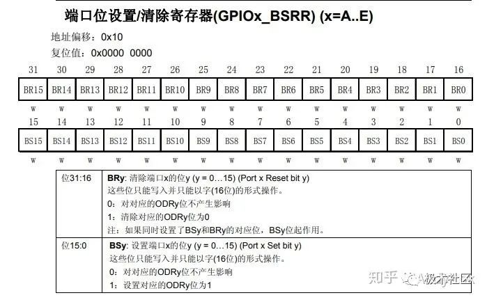
We will take the registers of the GPIOA peripheral as an example. We jump to the GPIO section in the manual (page 115), where there is a table listing the structure of the GPIO_BSRR register.
The function of this register is not important; we only need to understand how to read the register table:
The first row is the offset address. The offset address indicates the position of this register relative to the peripheral register segment. From the starting address table, we can see that the starting address of the GPIOA register segment is 0x4001_0800, and the offset address of GPIO_BSRR is 0x10. Therefore, the actual address of the GPIOA_BSRR register is 0x4001_0800 + 0x10 = 0x4001_0810.
The next two rows describe the bits of the register. The numbers on the boxes are the bit offset addresses, the names of the bits are in the middle of the boxes, and the read/write capability is indicated below the boxes. Here, all the boxes are marked with ‘w’, which means these bits are write-only.
According to the description below, if we want to clear ODR3 (a bit of another register), we need to write 1 to BR3. This operation is actually writing 0x1 << 19 (a 32-bit unsigned integer with all bits 0 except for bit 19) to the memory address 0x4001_0810.
Using Rust to operate is as follows:
core::ptr::write_volatile(0x4001_0810 as *mut u32, 1 << 19);
GPIO (General Purpose Input/Output)
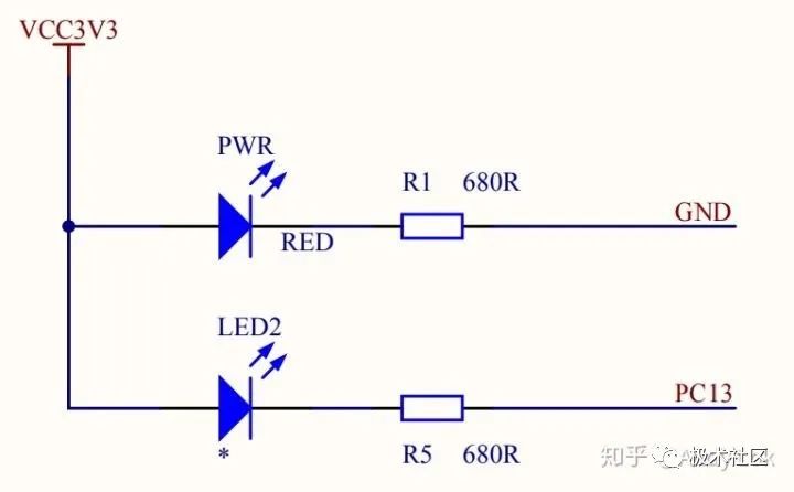
The principle of Blinky is very simple; just periodically change the level of the pin connected to the LED to make it blink. By examining the circuit schematic of the core board, we can find that the LED is connected to pin PC13, and the schematic shows that the LED uses a common anode connection, which means that the LED will light up when the pin outputs a low level:
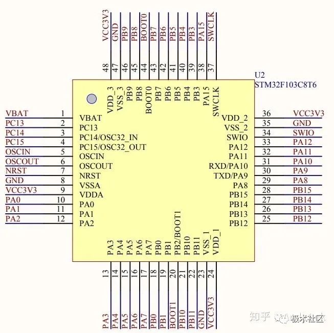
STM32F103C8T6 Pin Diagram
Note: On some STM32F103 core boards, the LED is connected to pin PB12, so check the schematic to confirm.
The pins in STM32 are divided into multiple groups such as GPIOA, GPIOB, GPIOC, GPIOD, etc., with each group controlling 16 pins, and each group is an independent peripheral.
Here, we need to learn about two key registers of GPIO: the configuration register (GPIOx_CRL, GPIOx_CRH) and the set/reset register (GPIOx_BSRR). (The ‘x’ in the register names corresponds to the GPIO groups A, B, C, etc.)
GPIO Configuration Register
The pins of the microcontroller often have multiple functions, such as input or output, so the function must be configured through the configuration register before using the pins.
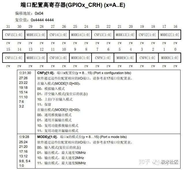
We notice that there are two configuration registers, GPIOx_CRL and GPIOx_CRH, which are actually the high and low parts of the configuration register. The low register (GPIOx_CRL) is responsible for configuring pins 0 to 7, while the high register (GPIOx_CRH) is responsible for configuring pins 8 to 15.
GPIO has the following modes:
-
-
-
-
-
-
-
Push-Pull Multiplexed Function – Open-Drain Multiplexed Function
Input can be understood as reading the level on the pin, while output is controlling the pin level. Since we want to light up the LED by controlling the pin level, we choose the output mode here.
The output mode has two types: Push-Pull Output and Open-Drain Output. In Push-Pull Output mode, the pin can output both high and low levels, but the current driving capability is relatively weak, suitable for communication with digital components or driving LEDs; Open-Drain Output only has low level and cutoff states, so a pull-up resistor (one end connected to power and the other end to the pin) is needed to output a high level in the cutoff state. Open-Drain Output has a stronger current driving capability and is suitable for current-driven applications.
Here we can just choose the simplest Push-Pull Output mode.
By consulting the manual, we can find the structure of the configuration register (page 114):
Pin PC13 corresponds to the MODE13 and CNF13 bits in the register; we will set MODE13 to output mode, which is 0x11 (maximum speed refers to the maximum level switching frequency, any value can be chosen here), and then set CNF13 to 0x00 to enable Push-Pull Output.
The Set/Reset Register is specifically used to control the output level of the pins. Writing 1 to BR (R means Reset) will set the corresponding pin to low level, while writing 1 to BS (S means Set) will set the corresponding pin to high level. The operation is very simple, so we won’t elaborate on it here.
The bus refers to the previously mentioned time buses APB1 and APB2. Any peripheral in the microcontroller needs to obtain time signals from the bus; however, after the microcontroller is reset, all peripherals are turned off by default to save energy. Therefore, the bus switch needs to be manually turned on before using the peripherals.
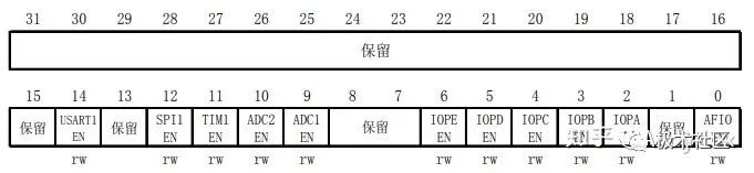
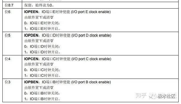
RCC (Reset and Clock Control) is responsible for configuring the time bus of the microcontroller, and its APB2ENR register is used to turn on or off peripherals on the APB2 bus. Since the GPIO peripheral is located on the APB2 bus, we look for the RCC_APB2ENR register (page 95):
From the figure, we can see that writing 1 to IOPCEN of APB2ENR will enable the GPIOC peripheral.
We open the project established in the previous article and modify src/main.rs to restore it to the minimum compilable version:
#![no_std]#![no_main] extern crate panic_halt;use core::ptr;use cortex_m::asm;use cortex_m_rt::entry;use stm32f103xx;#[entry] fn main() -> ! { asm::nop(); loop { } }
Modify the dependencies in Cargo.toml.Here, we are not using the register features of stm32f103xx yet; we just need the compiler to automatically link its provided interrupt vector table, otherwise it won’t compile:
[dependencies] cortex-m = "0.5.8" cortex-m-rt = "0.6.5" panic-halt = "0.2.0" stm32f103xx = "0.11"
We define the addresses of the registers based on the information in the manual:
const RCC_APB2ENR: *mut u32 = (0x4002_1000 + 0x18) as *mut u32;const GPIOC_CRH: *mut u32 = (0x4001_1000 + 0x04) as *mut u32;const GPIOC_BSRR: *mut u32 = (0x4001_1000 + 0x10) as *mut u32;
Next, we define the bit offset for the registers we will use:
const APB2ENR_IOPCEN: usize = 4;const CRH_MODE13: usize = 20;const BSRR_BS13: usize = 13;const BSRR_BR13: usize = 13 + 16;
Modify the main function.
#[entry]fn main() -> ! { unsafe {// Enable GPIOC ptr::write_volatile(RCC_APB2ENR, 1 << APB2ENR_IOPCEN);// Configure GPIOC - PC13 as Push-Pull Output ptr::write_volatile(GPIOC_CRH, 0b0011 << CRH_MODE13);// Reset PC13 to output low level ptr::write_volatile(GPIOC_BSRR, 1 << BSRR_BR13); } loop { }}
Note that we use ptr::write_volatile() for memory write operations because if we use ptr::write(), the compiler may optimize away the memory write operation or change the execution order, which can improve efficiency in memory operations but will completely alter our program’s intent when it comes to registers, leading to unpredictable consequences.Similarly, for reading from registers, we cannot use ptr::read() but must use ptr::read_volatile().
At this point, compiling and running will light up the LED.
Next, we create a simple delay function:
fn delay() {for _ in 0..2_000 {asm::nop(); }}
Here we use an assembly function nop, which stands for No Operation.It will take one CPU clock cycle, and we loop it to get a visually perceptible delay.
Actually, according to the clock speed of Cortex-M3 at 72MHz, a delay of 2000 cycles should be below the millisecond level. However, this delay can reach about half a second. This is because when the microcontroller starts, the chip defaults to a fast startup but low-frequency internal clock, which is around 40kHz. Generally, we need to set the RCC register to switch the clock source to an external high-speed clock after reset; we will discuss this in detail later.
loop { delay();// Reset: output low level, light up LED unsafe { ptr::write_volatile(GPIOC_BSRR, 1 << BSRR_BR13); } delay();// Set: output high level, LED off unsafe { ptr::write_volatile(GPIOC_BSRR, 1 << BSRR_BS13); }}
Thus, our register version of Blinky is complete!Here is the complete code:
#![no_std]#![no_main]extern crate panic_halt;use core::ptr;use stm32f103xx;use cortex_m::asm;use cortex_m_rt::entry;const RCC_APB2ENR: *mut u32 = (0x4002_1000 + 0x18) as *mut u32;const GPIOC_CRH: *mut u32 = (0x4001_1000 + 0x04) as *mut u32;const GPIOC_BSRR: *mut u32 = (0x4001_1000 + 0x10) as *mut u32;const APB2ENR_IOPCEN: usize = 4;const CRH_MODE13: usize = 20;const BSRR_BS13: usize = 13;const BSRR_BR13: usize = 13 + 16;#[entry]fn main() -> ! { unsafe {// Enable GPIOC ptr::write_volatile(RCC_APB2ENR, 1 << APB2ENR_IOPCEN);// Configure GPIOC - PC13 as Push-Pull Output ptr::write_volatile(GPIOC_CRH, 0b0011 << CRH_MODE13);// Reset PC13 to output low level ptr::write_volatile(GPIOC_BSRR, 1 << BSRR_BR13); } loop { delay();// Reset: output low level, light up LED unsafe { ptr::write_volatile(GPIOC_BSRR, 1 << BSRR_BR13); } delay();// Set: output high level, LED off unsafe { ptr::write_volatile(GPIOC_BSRR, 1 << BSRR_BS13); } }}fn delay() {for _ in 0..2_000 { asm::nop(); }}
The code above uses the method for operating registers in C, which is simple and direct. Although this is usable, it is clear that the semantics of such operations are very vague, and one often needs to repeatedly refer to the manual. Moreover, this method heavily uses unsafe memory operations, making it easy to make human errors. Fortunately, Rust provides us with safer abstractions that can greatly improve the above two issues.
The stm32f103xx library safely encapsulates the register operation interfaces, and it is automatically generated by svd2rust, which eliminates human errors. Its documentation can be found here.
Let’s see how to use this library:
// Get Peripheralslet dp = stm32f103xx::Peripherals::take().unwrap();// Enable GPIOCdp.RCC.apb2enr.write(|w| w.iopben().enabled());
The first line, stm32f103xx::Peripherals::take(), will only return Some(dp) on the first call, thus avoiding data races caused by multiple instances of registers.
Peripherals is a structure that has the interface definitions for all peripherals, such as RCC here. We can write to the apb2enr register of RCC; the read and write operations of the register are encapsulated in a closure, allowing the library to perform some safety operations (resetting register values or disabling interrupts) before and after reading and writing. ‘w’ is the writer for apb2enr, and calling w.iopben().enabled() is equivalent to the previous unsafe memory write, and zero-cost; the compiled instructions generally won’t differ.
Similarly, we can rewrite the operations for GPIOC as follows:
// Configure PC13dp.GPIOC.crh.write(|w| w.mode13().output().cnf13().push());// Setdp.GPIOC.bsrr.write(|w| w.bs13().set());// Resetdp.GPIOC.bsrr.write(|w| w.br13().reset());
#![no_std]#![no_main]extern crate panic_halt;use core::ptr;use stm32f103xx;use cortex_m::asm;use cortex_m_rt::entry;#[entry]fn main() -> ! {// Get Peripherals let dp = stm32f103xx::Peripherals::take().unwrap();// Enable GPIOC dp.RCC.apb2enr.write(|w| w.iopben().enabled());// Configure PC13 dp.GPIOC.crh.write(|w| w.mode13().output().cnf13().push()); loop { delay();// Reset: output low level, light up LED dp.GPIOC.bsrr.write(|w| w.br13().reset()); delay();// Set: output high level, LED off dp.GPIOC.bsrr.write(|w| w.bs13().set()); }}fn delay() {for _ in 0..2_000 { asm::nop(); }}
Compared to C-style register operations, svd2rust encapsulates all register address information, and no unsafe code is needed, ensuring that no memory errors occur in Rust.
Blinky: Further Abstraction
The performance of stm32f103xx is impressive, but it has not fully explored the potential of Rust. The embedded working group provides us with the embedded-hal abstraction library, and stm32f103xx-hal is the specific implementation of embedded-hal on stm32f103. The stm32f103xx-hal library further abstracts and encapsulates the logical details of register operations based on stm32f103xx. For example, stm32f103xx-hal can automatically enable the apb2enr bus switch before we use GPIOC. Similarly, this library is also zero-cost.
Modify Cargo.toml to add dependencies:
[dependencies.stm32f103xx-hal]features = ["rt"]git = "https://github.com/japaric/stm32f103xx-hal"
In src/main.rs, import hal:
extern crate stm32f103xx_hal as hal;use hal::prelude::*;
The hal::prelude defines many traits that are implemented by default on peripheral structures (like RCC) to provide the constrain() conversion function.constrain() will convert the stm32f103xx peripheral instance into the more abstract hal structure.
let dp = stm32f103xx::Peripherals::take().unwrap();// Convert RCC register structure to further abstract hal structurelet mut rcc = dp.RCC.constrain();// Get GPIOC instance, automatically enabling the bus switchlet mut gpioc = dp.GPIOC.split(&mut rcc.apb2);// Get PC13 instance and configure the pinlet mut led = gpioc.pc13.into_push_pull_output(&mut gpioc.crh);// Output high levelled.set_high();// Output low levelled.set_low();
#![no_std]#![no_main]extern crate panic_halt;extern crate stm32f103xx_hal as hal;use core::ptr;use stm32f103xx;use cortex_m::asm;use cortex_m_rt::entry;use hal::prelude::*;#[entry]fn main() -> ! {// Get Peripherals let dp = stm32f103xx::Peripherals::take().unwrap();// Convert RCC register structure to further abstract hal structure let mut rcc = dp.RCC.constrain();// Get GPIOC instance, automatically enabling the bus switch let mut gpioc = dp.GPIOC.split(&mut rcc.apb2);// Get PC13 instance and configure the pin let mut led = gpioc.pc13.into_push_pull_output(&mut gpioc.crh); loop { delay();// Output low level led.set_low(); delay();// Output high level led.set_high(); }}fn delay() {for _ in 0..2_000 { asm::nop(); }}
This article is lengthy, covering the principles of registers all the way to memory operation methods, and then demonstrating how Rust’s powerful abstraction capabilities can hide scattered memory operations behind safe operation interfaces. Additionally, based on embedded-hal, we further abstract the logic of register operations to obtain a safe and easy-to-use API, allowing for flexible selection of abstraction levels based on needs. I believe readers can already feel the significant advantages of Rust in the embedded field compared to C.
Copyright belongs to the original author. If there is any infringement, please contact for deletion.
END


关于安芯教育


安芯教育是聚焦AIoT(人工智能+物联网)的创新教育平台,提供从中小学到高等院校的贯通式AIoT教育解决方案。
安芯教育依托Arm技术,开发了ASC(Arm智能互联)课程及人才培养体系。已广泛应用于高等院校产学研合作及中小学STEM教育,致力于为学校和企业培养适应时代需求的智能互联领域人才。