A long time ago, in Denmark, there was a king named Harald Blatand, who unified the constantly quarreling tribes of Denmark into a complete nation. The king had a nickname called “blátǫnn,” which translates to Bluetooth in English. In ancient Nordic runes, the initials of the king’s name ‘H’ and ‘B’ are written differently than today:
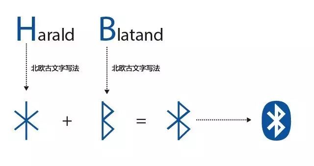
Indeed, this is the origin of the Bluetooth symbol and name.
The once-giant communication company Sony Ericsson created Bluetooth communication technology in 1994, borrowing this story.
Time flies, Sony Ericsson has come down from its pedestal, but “Bluetooth” has once again achieved “unification,” becoming the global standard for communication protocols.
In the past, infrared remote control was the dominant technology for proximity control. It was mature, cost-effective, and widely used, but infrared transmission had two insurmountable weaknesses:
1. Extremely strong directionality and very short communication distance;
2. One-way communication (unless equipped with both transmission and receiving modules);
In infrared communication, one side can only issue commands or only receive commands. Bluetooth transmission is different; within the signal coverage area, it does not require direction, and the signal can even penetrate walls; communication devices can switch between master and slave states at any time, allowing information to be both received and sent.
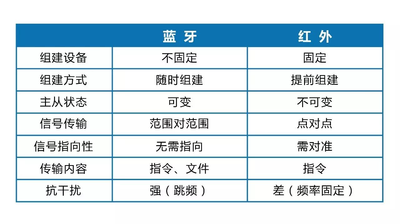
Note: The comparison ignores the point-to-point file transfer scenario of infrared.
This freedom and convenience have allowed Bluetooth applications to quickly cover our daily life needs: Bluetooth headsets, Bluetooth mice, smart wristbands, and even remote controls for TVs or smart boxes. Bluetooth has almost seamlessly integrated into our daily lives as a standard feature of electronic devices.
Lego is no exception; both the WeDo and EV3 kits support Bluetooth, and the WeDo kit can only be programmed and controlled via Bluetooth. Although Arduino boards do not come with Bluetooth functionality by default (except for Arduino BT), they can easily be extended for Bluetooth.
Let’s take a look at our main character today:
HC-05 Integrated Bluetooth Module
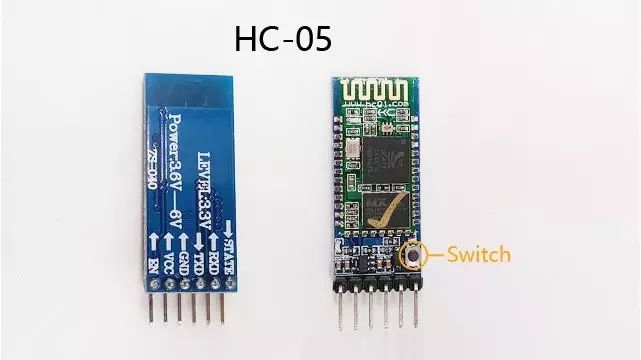
HC-05 ZS-040 Bluetooth Module
This module consists of a breakout board and a daughter board. The breakout board has a built-in voltage divider, allowing it to adapt to a voltage input of 3.6V~6V, but the communication interface voltage of the Bluetooth daughter board is limited to 3.3V; excessive voltage input may damage the daughter board (don’t ask me how I know this).
1.0 Interface and Wiring Diagram
RX is the signal input interface for the Bluetooth daughter board, and TX is the signal output interface; both operate at 3.3V. Based on Arduino’s definition of high and low levels, anything above 3V can be recognized as a high level. The TX interface’s 0V/3.3V state switch can be recognized as a high/low level switch, so the TX interface can be connected directly to Arduino. However, RX, as the input end of the daughter board, must adhere to the 3.3V input limit; when in use, the voltage signal output from Arduino needs to be stepped down, and the step-down principle is based on the voltage divider law learned in physics:
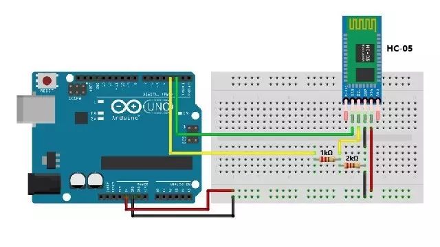
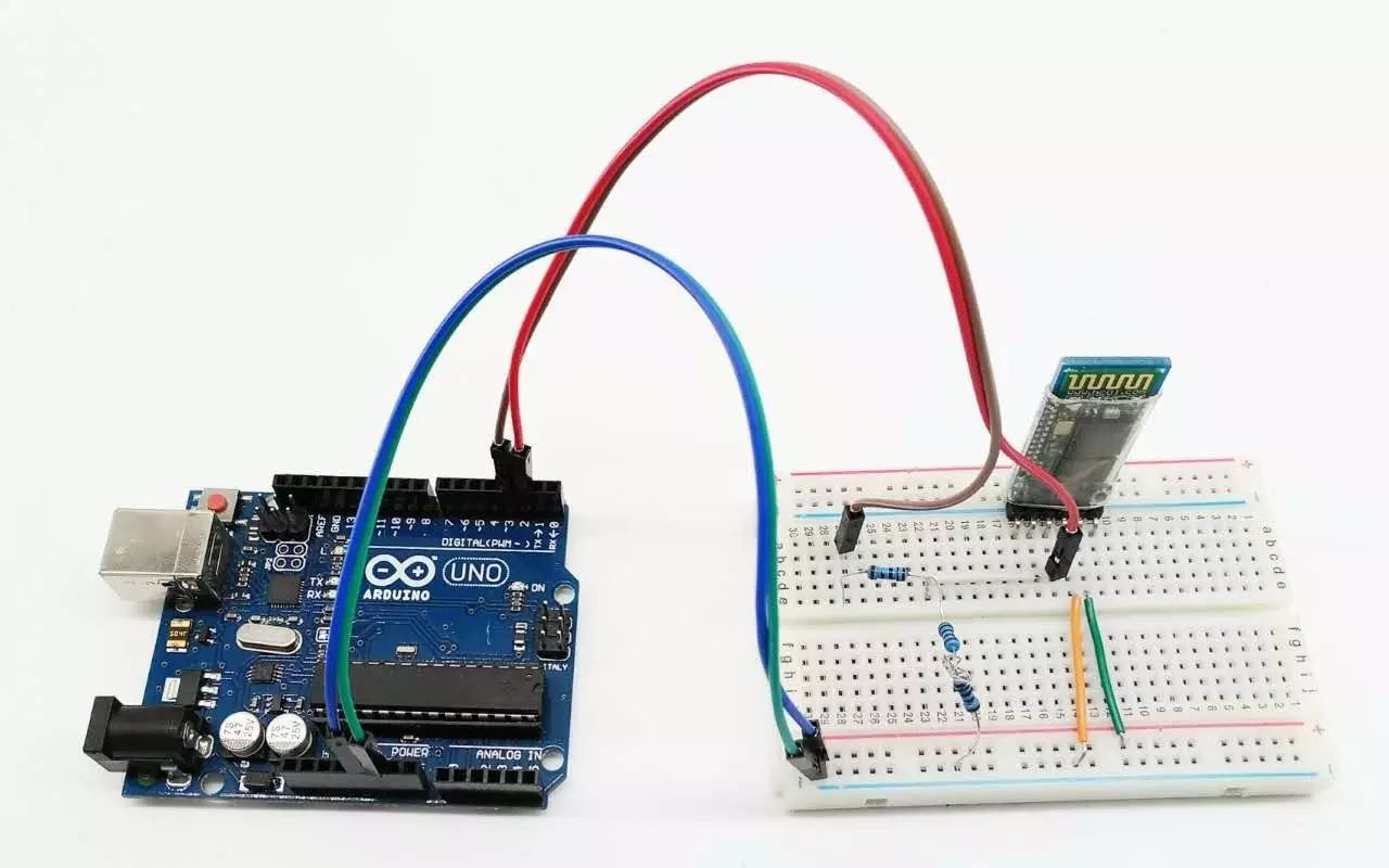
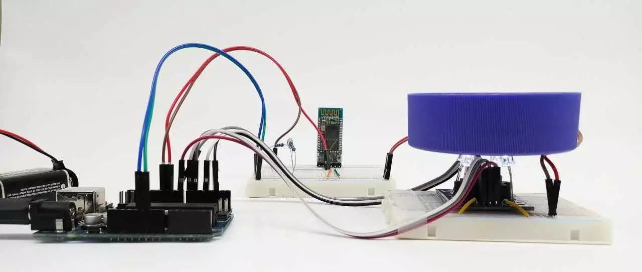
Wiring schematic and breadboard wiring diagram
RX and GND divide the voltage to get approximately 3.33V, satisfying the voltage requirements of the daughter board.
2.0 Bluetooth Configuration
Completing the device wiring does not mean the Bluetooth module can be used directly; at this point, various parameters of the Bluetooth device, such as communication port, connection password, master/slave status, etc., are still in factory settings, which we need to configure according to our needs. Configuration parameters can be saved even after power off, so it only needs to be set once.
After powering on the board, it defaults to working mode; to enter configuration mode, you need to first press and hold the SWITCH button on the Bluetooth board, then power on. When the blue indicator light on the board blinks slowly with a 2-second cycle, it indicates that it has entered configuration mode.
Configuration Mode
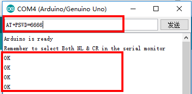
The configuration process involves sequentially changing parameters such as communication port, device name, connection PIN code, master/slave status, and checksum to meet subsequent program requirements. The configuration process can utilize Arduino’s serial forwarding, where Arduino forwards the commands we input into the serial monitor to the HC-05, completing the setup.
AT+COMMAND is used for the setup, and common configuration commands are as follows:
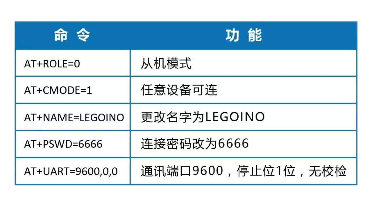 If the setup is successful, an OK prompt will be returned:
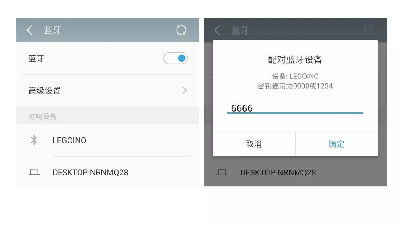
After completing the setup, power on again, and the board will start working according to the new configuration, and it can be searched and matched by devices like mobile phones:
3.0 Establishing Communication with Mobile Phones
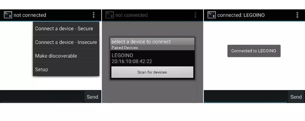
To achieve Bluetooth control, you must first communicate with the device. Here we need a mobile app: Bluetooth Terminal. After downloading and installing, open the app to view nearby Bluetooth devices and select “LEGOINO” to complete the connection.
 Thus, we pick up the phone and communicate with the nearby Arduino:

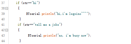
Of course, all these interactions are pre-set by us:
 Program Screenshot
Throughout the process, Arduino implements information forwarding and judgment: forwarding information from the serial monitor to the Bluetooth module or displaying information received by the Bluetooth module in the serial monitor; if a pre-set command is received, it executes the corresponding operation.
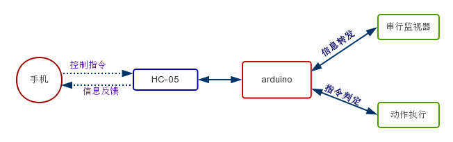 Command Propagation Flowchart
4.0 Control
Once the communication link is established, controlling is just a step away; you only need to modify keywords like “hi” and the corresponding program execution code:

Code Screenshot
Let’s test it:

Controlling a relay is too simple, so let’s switch to a color recognition module:
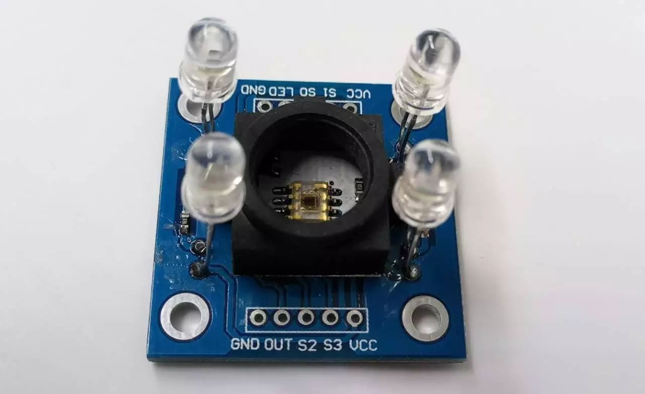 Color recognition module, returns the RGB value of the color
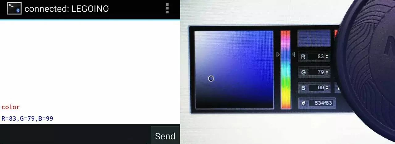
Recognition process:
Let’s take a look at the recognized color:
5. Unexpected Gifts
Being able to remotely control switches and return recognized colors allows for more complex functions.
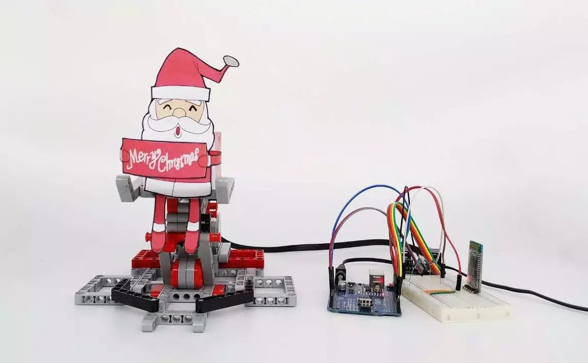
Christmas is coming; if you want to send blessings to someone and stand out, you can try Lego~
So I casually made a Lego device again:


Lego Ladder
This device can be conveniently hidden in a box or behind a monitor:

Go surprise (scare) him/her~
Wishing everyone a Merry Christmas in advance~

—————————————————————————————————
Postscript
Unknowingly, adhering to the idea of “Lego Structure + Arduino Function“, the article series “When Lego Meets Arduino” has already reached its fifth installment, covering topics such as: LEGO Arduino control board, Lego servo control (gear speed and rotation mapping), IoT control, infrared control, Bluetooth control, etc., introducing the principles and methods of implementation; it also includes the use of modules like PM2.5 dust detectors, W5100 network expansion boards, relays, infrared devices, Bluetooth modules, and color recognition, striving to present the unique charm of both and the sparks that fly when combined.
Careful readers will find that the entire series of articles is based on the idea of “Arduino Detector—Arduino—Lego Motor—Lego Structure” and has not used Lego detectors or non-Lego power structures; upcoming articles will focus on different themes from various angles, aiming to bring richer application scenarios and better articles to everyone.
Links to previous articles in this series can be accessed by clicking:
-
“When Lego Meets Arduino: How to Control Lego Components Externally”
-
“When Lego Meets Arduino: Lego PM2.5 Detector”
-
“When Lego Meets Arduino: Lego Calls You to Dinner~”
-
“When Lego Meets Arduino: Proximity Control via Infrared”
Due to space limitations, many contents such as detector settings, parameter adjustments, libraries used, program design ideas, and code cannot be presented in this article; to facilitate communication with everyone and gather great ideas and needs, we have created a WeChat group for discussion. Everyone is welcome to join the group.
 Scan to add “Xuetangjun”
Join the teacher discussion group of Science and Technology Classroom