1. Synchronous and Asynchronous Transmission
1.1 Concepts and Examples
Using everyday examples to illustrate what synchronous and asynchronous mean:
Synchronous: A friend calls to say they are coming to my house for dinner, and I wait for them at home.
Asynchronous: A friend arrives at my house unexpectedly without prior notice.
The difference lies in whether there is a method to “set an agreed time”.
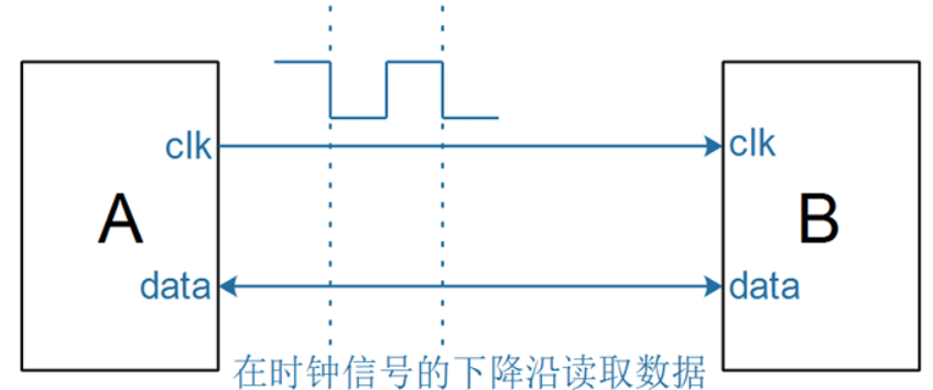
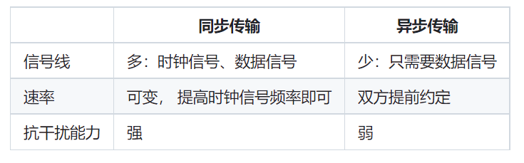
In electronic products, when using synchronous transmission, it generally involves two signals:
Clock signal: Used to notify the other party to read the data.
Data signal: Used to transmit data.
An example of synchronous transmission is as follows:
Clock signal: Making a phone call serves as an agreement.
Data signal: Transmitting data.
Asynchronous transmission example is as follows:
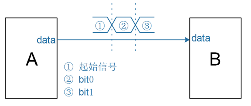
When using asynchronous signal transmission, both parties adhere to the same agreement:
Start signal: The sender can notify the receiver, “Attention, I am about to start transmitting data.”
Data representation: How to represent logic 1 and how to represent logic 0.
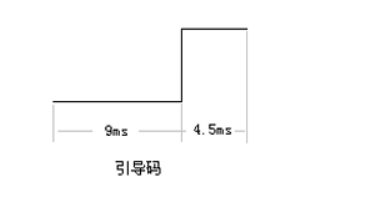
Taking the infrared remote control decoder as an example, the data format it sends to the microcontroller is as follows:
Start signal: The decoder emits a low level of 9ms and a high level of 4.5ms, simultaneously notifying the other party, “It has started.”
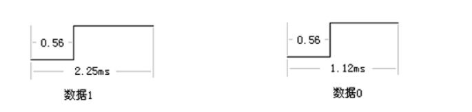
Representing one data bit:
Logic 1: 0.56ms low level + 1.69ms high level
Logic 0: 0.56ms low level + 0.56ms high level
As long as both the receiver and sender adhere to this agreement, data can be transmitted using a single wire.
1.2 Differences
2. UART Protocol and Operation Methods
2.1 UART Protocol
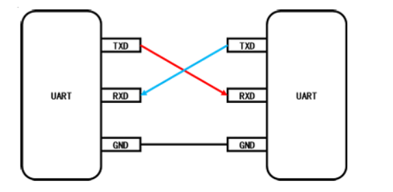
Universal Asynchronous Receiver Transmitter, abbreviated as UART, is used for transmitting serial data: when sending data, the CPU writes parallel data into UART, which serially sends it out over a single wire according to a specific format; when receiving data, UART detects the signals on another wire, collects the serial data into a buffer, and the CPU can read the data from UART. Data is transmitted between UARTs in full-duplex mode, with the simplest wiring method requiring only three wires: TxD for sending data, RxD for receiving data, and GND for providing a reference voltage for both parties, as illustrated below:
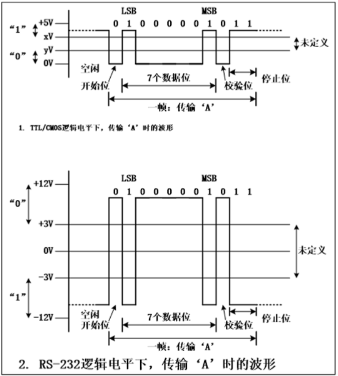
UART uses standard TTL/CMOS logic levels (0-5V, 0-3.3V, 0-2.5V, or 0-1.8V) to represent data, where a high level represents 1 and a low level represents 0. For long-distance transmission, to enhance the data’s anti-interference capability and increase transmission length, TTL/CMOS logic levels are usually converted to RS-232 logic levels, where 3-12V represents 0 and -3 to -12V represents 1.
TxD and RxD data lines transmit data in bits as the smallest unit. A frame consists of several bits that have complete meaning and cannot be divided, including start bits, data bits, parity bits (if necessary), and stop bits. Before sending data,
UARTs must agree on the data transmission rate (the time each bit occupies, the reciprocal of which is called baud rate), and the data transmission format (how many data bits, whether to use parity bits, whether it is odd or even parity, and how many stop bits). The data transmission process is as follows:
• The data line is normally in an “idle” state (1 state).
• When data is to be sent, UART changes the TxD data line state (to 0 state) and maintains it for 1 bit of time—this way, the receiver detects the start bit and waits for 1.5 bits of time before starting to check the data line state bit by bit to obtain the transmitted data.
• A UART frame can contain 5, 6, 7, or 8 data bits, with the sender changing the data line state bit by bit to send them out, starting with the least significant bit.
• If using parity, after sending the data bits, UART must also send 1 parity bit. There are two parity methods: odd parity and even parity—among the data bits and the parity bit, the number of “1s” is either odd or even.
• Finally, a stop bit is sent, and the data line returns to the “idle” state (1 state). The following diagram demonstrates the waveform corresponding to TTL/CMOS logic levels and RS-232 logic levels when transmitting the character “A” (binary value 0b01000001) using 7 data bits, even parity, and 2 stop bits.
Once both parties have agreed on “the time to transmit one bit of data,” they can calculate how many bits can be transmitted in one second, which is referred to as “bit rate,” often also called “baud rate.” What is the relationship between the two?
Assuming sender A can precisely control the signal voltage, and receiver B can also accurately identify the voltage, both parties agree:
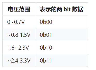
To transmit a byte of data, for example, 0x78, whose binary representation is 0b01111000, only requires 8 transmissions (assuming the voltage changes every 1ms, and assuming the least significant bit is sent first):
• At 1ms, A sets the voltage to 0V, B recognizes the voltage and interprets it as bit0 being 0.
• At 2ms, A sets the voltage to 0V, B recognizes the voltage and interprets it as bit1 being 0.
• At 3ms, A sets the voltage to 0V, B recognizes the voltage and interprets it as bit2 being 0.
• At 4ms, A sets the voltage to 3.3V, B recognizes the voltage and interprets it as bit3 being 1.
• At 5ms, A sets the voltage to 3.3V, B recognizes the voltage and interprets it as bit4 being 1.
• At 6ms, A sets the voltage to 3.3V, B recognizes the voltage and interprets it as bit5 being 1.
• At 7ms, A sets the voltage to 3.3V, B recognizes the voltage and interprets it as bit6 being 1.
• At 8ms, A sets the voltage to 0V, B recognizes the voltage and interprets it as bit7 being 0.
It takes 8ms to transmit 8 states, transmitting 8 bits of data: baud rate = bit rate.
Therefore, baud rate: the number of signal states transmitted per second (number of waveforms). Bit rate: the number of bits of data transmitted per second. If one waveform can represent N bits, then: baud rate * N = bit rate.
2.2 STM32H5 UART Hardware Structure

2.3 RS485 Protocol
When transmitting data using the RS485 protocol, the circuit diagram is as follows:
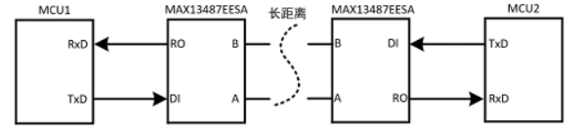
In the RS485 protocol, differential signal lines A and B are used to transmit data: the voltage difference between the two lines of + (2 to 6)V represents logic 1, while a voltage difference of – (2 to 6)V represents logic 0. It operates in half-duplex mode: when MCU1 wants to send data, it sends the data from the TxD pin to the level conversion chip MAX13487EESA, which converts the TxD signal into a differential signal and passes it to another level conversion chip MAX13487EESA, which in turn converts it to TTL levels to be sent to the RxD pin of MCU2. If MCU2 wants to send data to MCU1, it must wait for the differential signal line to be idle.
From a software perspective, using RS485 is no different from using ordinary UART.
3. UART Programming
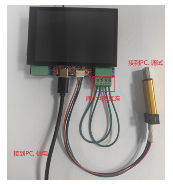
3.1 Hardware Connection
Connect the wires as shown in the diagram: debugging, powering, and interconnecting two 485 devices.
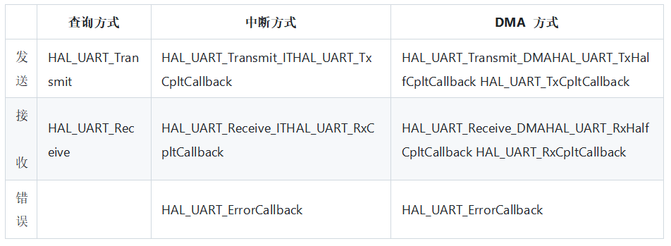
3.2 Three Programming Methods
Based on the UART hardware structure, there are 3 programming methods:
Polling Method:
To send data, first write the data into the TDR register, then check if TDR is empty before returning. Alternatively, you can check if TDR is empty first and then write the data.
To read data, first check if RDR is not empty, then read RDR to get the data.
Interrupt Method:
This method is more efficient and can avoid data loss when receiving data.
To send data, enable the “TXE” interrupt (transmit register empty interrupt). In the TXE interrupt handler, take one data from the program’s send buffer and write it to TDR. When the TXE interrupt occurs again, take the next data from the program’s send buffer and write it to TDR.
For receiving data, enable the “RXNE” interrupt (receive register not empty) at the beginning. This way, when UART receives one data, it will trigger an interrupt, and in the interrupt program, read RDR to get the data and store it in the program’s receive buffer. When the program wants to read serial data, it can directly read from the receive buffer.
The involved “send buffer” and “receive buffer” are particularly suitable for using a “circular buffer”.
DMA Method:
Using the interrupt method, during data transmission and reception, interrupts will occur, and the CPU must execute the interrupt handler. An alternative method is Direct Memory Access (DMA), which can transfer data directly between two devices without CPU involvement.
The block diagram is as follows:
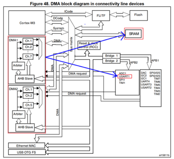
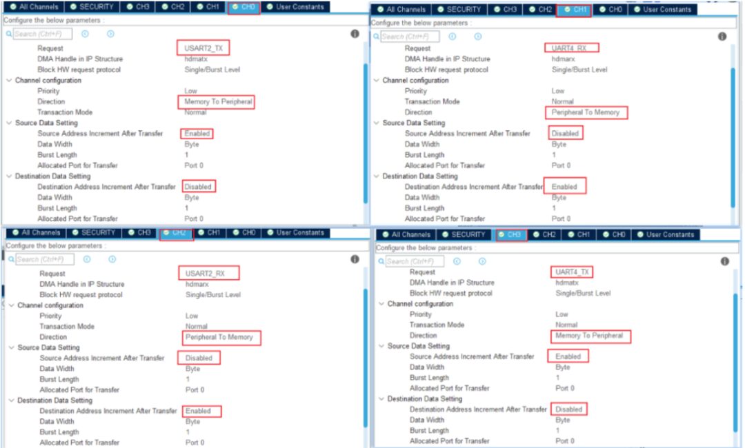
After setting up DMA (source, destination, address increment direction, length of data to read each time, number of reads), DMA will automatically transfer data between SRAM and UART:
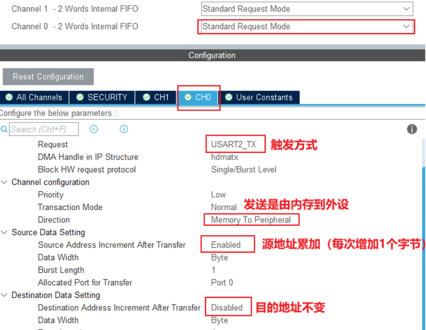
When sending: DMA gets data from SRAM and writes it to UART’s TDR register (source address is memory, needs to increment; destination is TDR, TDR address remains unchanged).
When receiving: DMA gets data from UART’s RDR register and writes it to SRAM (source address is RDR, RDR address remains unchanged; destination is memory, needs to increment).
After the specified data transfer is complete, a DMA interrupt is triggered; during data transfer, there are no interrupts, and the CPU does not need to process anything.
The function is as follows:
3.3 Polling Method
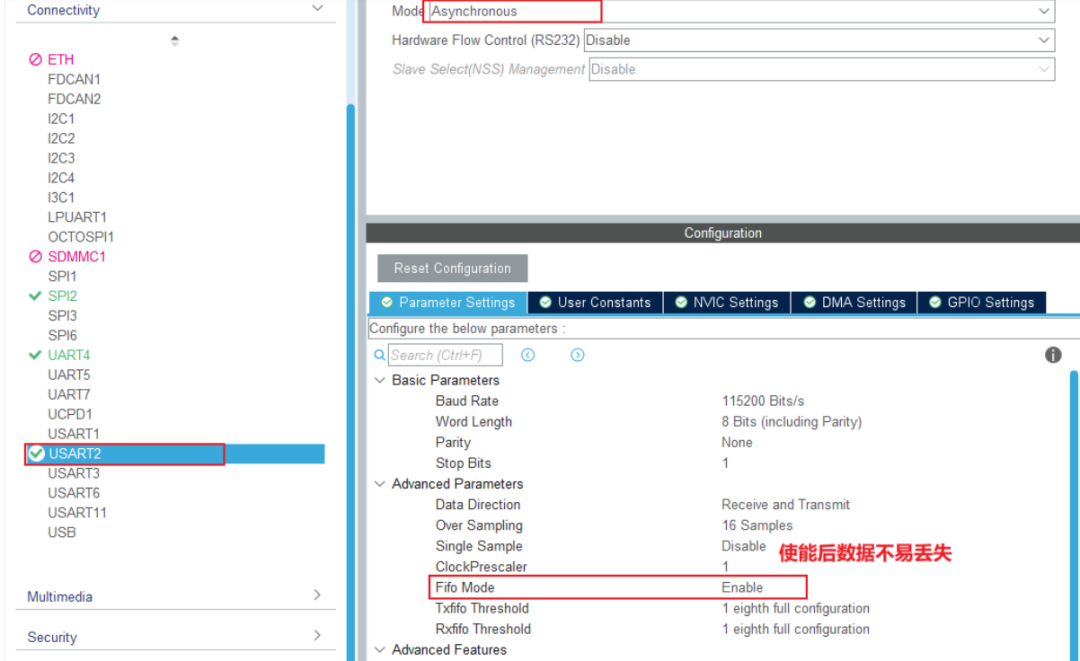
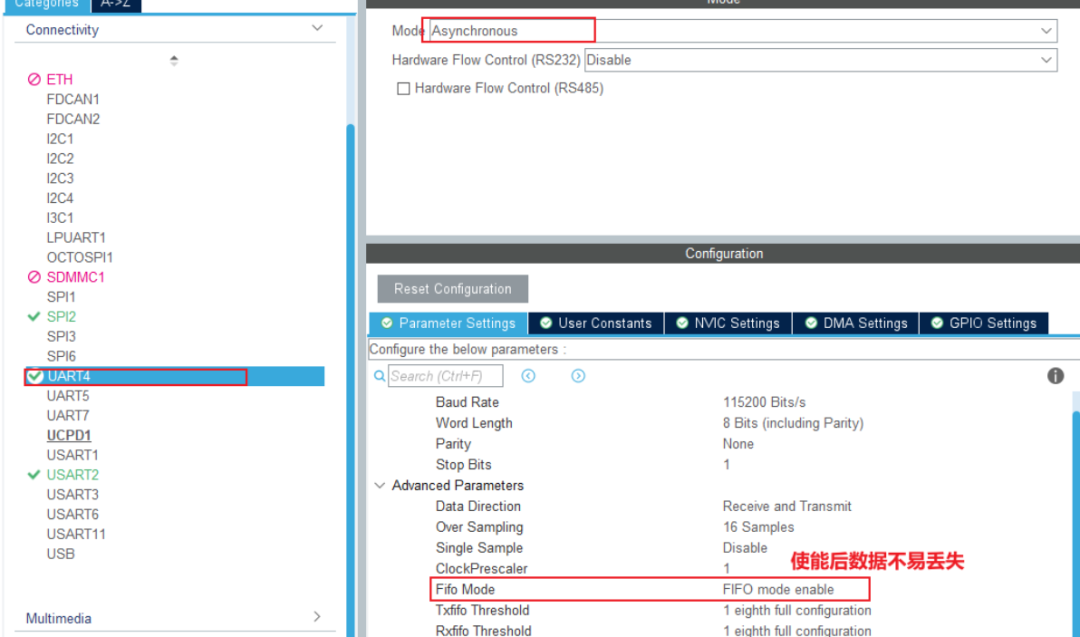
3.3.1 STM32CubeMX Configuration
3.3.2 Code Call
app_freertos.c
extern UART_HandleTypeDef huart4;extern UART_HandleTypeDef huart2;
static void CH1_UART2_TxTaskFunction( void *pvParameters )  {  uint8_t c = 0;    while (1)  {    /* Send data */    HAL_UART_Transmit(&huart2, &c, 1, 100);    vTaskDelay(500);    c++;  }}
static void CH2_UART4_RxTaskFunction( void *pvParameters )  {  uint8_t c = 0;  int cnt = 0;  char buf[100];  HAL_StatusTypeDef err;    while (1)  {    /* Receive data */    err = HAL_UART_Receive(&huart4, &c, 1, 100);        /* Display on OLED */      if (!err)    {      sprintf(buf, "Recv Data : 0x%02x, Cnt : %d", c, cnt++);      Draw_String(0, 0, buf, 0x0000ff00, 0);    }  }}
xTaskCreate(    CH1_UART2_TxTaskFunction,    "ch1_uart2_tx_task",    200,    NULL,    osPriorityNormal,    NULL);
xTaskCreate(    CH2_UART4_RxTaskFunction,    "ch2_uart4_rx_task",    200,    NULL,    osPriorityNormal,    NULL);
3.3.3 On-Site Experiment
Display the received character and count value on the OLED screen.
Disadvantage: When sending data, it has to wait until sending is complete, and data may be lost when receiving.
3.4 Interrupt Method
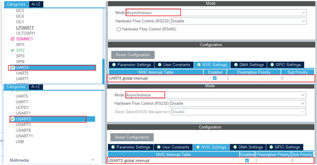
3.4.1 STM32CubeMX Configuration
3.4.2 Code Call
app_freertos.c
extern UART_HandleTypeDef huart4;extern UART_HandleTypeDef huart2;
static void CH1_UART2_TxTaskFunction( void *pvParameters )  {  uint8_t c = 0;    while (1)  {    /* Send data */    HAL_UART_Transmit_IT(&huart2, &c, 1, 100);    vTaskDelay(500);    c++;  }}
static void CH2_UART4_RxTaskFunction( void *pvParameters )  {  uint8_t c = 0;  int cnt = 0;  char buf[100];  HAL_StatusTypeDef err;    while (1)  {    /* Receive data */    err = HAL_UART_Receive_IT(&huart4, &c, 1, 100);        /* Display on OLED */      if (!err)    {      sprintf(buf, "Recv Data : 0x%02x, Cnt : %d", c, cnt++);      Draw_String(0, 0, buf, 0x0000ff00, 0);    }        else    {      HAL_UART_AbortReceive_IT(&huart4);//Terminate the interrupt function's reception    }  }}
xTaskCreate(    CH1_UART2_TxTaskFunction,    "ch1_uart2_tx_task",    200,    NULL,    osPriorityNormal,    NULL);
xTaskCreate(    CH2_UART4_RxTaskFunction,    "ch2_uart4_rx_task",    200,    NULL,    osPriorityNormal,    NULL);
usart.c
static volatile int g_uart2_tx_complete = 0;//Define global variable flag
static volatile int g_uart4_rx_complete = 0;
void HAL_UART_TxCpltCallback(UART_HandleTypeDef *huart){  if (huart == &huart2)//If from UART2  {    g_uart2_tx_complete = 1;  }}
int Wait_UART2_Tx_Complete(int timeout){  while (g_uart2_tx_complete == 0 && timeout)//Variable equals 0 and timeout not reached  {    vTaskDelay(1);    timeout--;  }  if (timeout == 0)//Timeout returns -1    return -1;  else  {    g_uart2_tx_complete = 0;//Not timed out returns 0    return 0;  }}
void HAL_UART_RxCpltCallback(UART_HandleTypeDef *huart){  if (huart == &huart4)  {    g_uart4_rx_complete = 1;  }}
int Wait_UART4_Rx_Complete(int timeout){  while (g_uart4_rx_complete == 0 && timeout)  {    vTaskDelay(1);    timeout--;  }  if (timeout == 0)    return -1;  else  {    g_uart4_rx_complete = 0;    return 0;  }}
3.4.3 On-Site Experiment
Display the received character and count value on the OLED screen.
Disadvantage: The receiving function must be called in advance for interrupt reception, which may lead to data loss.
3.5 DMA Method
3.5.1 STM32CubeMX Configuration
3.5.2 Code Call
app_freertos.c
extern UART_HandleTypeDef huart4;extern UART_HandleTypeDef huart2;
static void CH1_UART2_TxTaskFunction( void *pvParameters )  {  uint8_t c = 0;    while (1)  {    /* Send data */    HAL_UART_Transmit_DMA(&huart2, &c, 1, 100);    vTaskDelay(500);    c++;  }}
static void CH2_UART4_RxTaskFunction( void *pvParameters )  {  uint8_t c = 0;  int cnt = 0;  char buf[100];  HAL_StatusTypeDef err;    while (1)  {    /* Receive data */    err = HAL_UART_Receive_DMA(&huart4, &c, 1, 100);        /* Display on OLED */      if (!err)    {      sprintf(buf, "Recv Data : 0x%02x, Cnt : %d", c, cnt++);      Draw_String(0, 0, buf, 0x0000ff00, 0);    }        else    {      HAL_UART_DMA_STOP(&huart4);//Terminate the interrupt function's reception    }  }}
xTaskCreate(    CH1_UART2_TxTaskFunction,    "ch1_uart2_tx_task",    200,    NULL,    osPriorityNormal,    NULL);
xTaskCreate(    CH2_UART4_RxTaskFunction,    "ch2_uart4_rx_task",    200,    NULL,    osPriorityNormal,    NULL);
3.5.3 On-Site Experiment
Display the received character and count value on the OLED screen.
This section discusses the traditional DMA method, not involving the “idle interrupt,” which will be explained later. Disadvantage: The receiving function must be called in advance for interrupt reception, which may lead to data loss.
4. The Most Efficient UART Programming Method
4.1 IDLE Interrupt
IDLE is defined as: no data is received on the bus within the time of one byte.
When does the UART IDLE interrupt occur? The RxD pin is initially idle; does the IDLE interrupt occur continuously? No. When we enable the IDLE interrupt, it does not occur immediately; rather, it occurs only after at least one data has been received, and it is found that no new data has been received within the time of one byte.
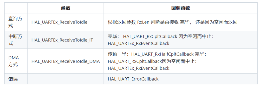
When receiving data using DMA, it can indeed improve CPU efficiency, but “it is impossible to predict how much data will be received,” and we want to process the received data as quickly as possible. What to do? For example, if I want to read 100 bytes of data, but the other party stops sending data after sending 60 bytes, what should I do? How do we determine that the data transmission has stopped? We can use the IDLE interrupt. In this case, there are three conditions for DMA transfer to end:
1. The specified amount of data has been received, for example, 100 bytes of data, and HAL_UART_RxCpltCallback is called.
2. The bus is idle: HAL_UARTEx_RxEventCallback is called.
3. An error occurs: HAL_UART_ErrorCallback is called.
Functions that use the IDLE state for reception are as follows:
4.2 DMA Sending/DMA+IDLE Receiving
Key points are three:
For sending: Use the “HAL_UART_Transmit_DMA” function.
For receiving: Call “HAL_UARTEx_ReceiveToIdle_DMA” at the beginning to start receiving.
In the callback function “HAL_UART_RxCpltCallback” or “HAL_UARTEx_RxEventCallback,” after reading and storing the data, call “HAL_UARTEx_ReceiveToIdle_DMA” again to start receiving.
5. Using UART in RTOS
5.1 Program Framework
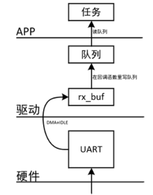
The focus of this program is how to efficiently receive data:
Using DMA+IDLE interrupt for receiving data, it will store the data in a temporary buffer;
In the callback function: write the data from the temporary buffer to a queue, then re-enable DMA.
The application reads from the queue: if there is no data in the queue, it blocks.
The framework is as follows:
5.2 Writing the Program
app_freertos.c
extern UART_HandleTypeDef huart4;extern UART_HandleTypeDef huart2;
static void CH1_UART2_TxTaskFunction( void *pvParameters )  {  uint8_t c = 0;    while (1)  {    /* Send data */    HAL_UART_Transmit_DMA(&huart2, &c, 1, 100);    vTaskDelay(500);    c++;  }}
static void CH2_UART4_RxTaskFunction( void *pvParameters )  {  uint8_t c = 0;  int cnt = 0;  char buf[100];  HAL_StatusTypeDef err;    while (1)  {    /* Receive data */    err = UART4_GetData(&c);        /* Display on OLED */      if (err == 0)        {      sprintf(buf, "Recv Data : 0x%02x, Cnt : %d", c, cnt++);      Draw_String(0, 0, buf, 0x0000ff00, 0);    }    else    {      HAL_UART_DMA_STOP(&huart4);//Terminate the interrupt function's reception    }  }}
xTaskCreate(    CH1_UART2_TxTaskFunction,    "ch1_uart2_tx_task",    200,    NULL,    osPriorityNormal,    NULL);
xTaskCreate(    CH2_UART4_RxTaskFunction,    "ch2_uart4_rx_task",    200,    NULL,    osPriorityNormal,    NULL);
usart.c
static volatile int g_uart2_tx_complete = 0;static volatile int g_uart4_rx_complete = 0;static uint8_t g_rx_buffer[100];static QueueHandle_t g_xUART4_RX_Queue;
void HAL_UART_TxCpltCallback(UART_HandleTypeDef *huart){  if (huart == &huart2)  {    g_uart2_tx_complete = 1;  }}
int Wait_UART2_Tx_Complete(int timeout){  while (g_uart2_tx_complete == 0 && timeout)  {    vTaskDelay(1);    timeout--;  }  if (timeout == 0)    return -1;  else  {    g_uart2_tx_complete = 0;    return 0;  }}
void HAL_UART_RxCpltCallback(UART_HandleTypeDef *huart){  if (huart == &huart4)  {    g_uart4_rx_complete = 1;        /* write queue : g_uart4_rx_buf 100 bytes ==> queue */    for(int i = 0; i < 100; i++)  {      xQueueSendFromISR(g_xUART4_RX_Queue, &g_rx_buffer[i], NULL);    }    /* re_start DMA+IDLE rx */    HAL_UARTEx_ReceiveToIdle_DMA(&huart4, g_rx_buffer, 100);//Re-enable next reception  }}
int Wait_UART4_Rx_Complete(int timeout){  while (g_uart4_rx_complete == 0 && timeout)  {    vTaskDelay(1);    timeout--;  }  if (timeout == 0)    return -1;  else  {    g_uart4_rx_complete = 0;    return 0;  }}
5.3 Object-Oriented Encapsulation of UART
We use multiple UARTs: UART2, UART4. For initialization, we have the following functions:
void UART2_Rx_Start(void);void UART4_Rx_Start(void);For users, this is very unfriendly: as the number of UARTs increases, they need to remember and use multiple function names; when replacing a UART, they need to modify multiple pieces of code. For example, for the following code, when replacing it with UART4, lines 1 and 3 need to be modified to the functions of UART4:
uart2_init(115200, 'N', 8, 1); char *str = "www.100ask.net"; uart2_sendp(str, strlen(str), 100);Encapsulating UART operations into a structure can solve this problem. The main operations for UART include 4 functions: obtaining the device name (which traverses the structure array in uart_device.c), initializing, sending data, and receiving data. Thus, we can abstract the following structure:
struct UART_Device { char *name; int (*Init)( struct UART_Device *pDev, int baud, char parity, int data_bit, int stop_bit); int (*Send)( struct UART_Device *pDev, uint8_t *datas, uint32_t len, int timeout); int (*RecvByte)( struct UART_Device *pDev, uint8_t *data, int timeout);};This section constructs a “struct UART_Device” structure for UART2 and UART4, for example:
struct UART_Device g_uart2_dev = {"uart2", uart2_init, uart2_send, uart2_recvbyte};struct UART_Device g_uart4_dev = {"uart4", uart4_init, uart4_send, uart4_recvbyte};When using, the sample code is as follows:
struct UART_Device *pDev = &g_uart2_dev;pDev->Init(pDev, 115200, 'N', 8, 1);char *str = "www.100ask.net";pDev->Send(pDev, str, strlen(str), 100);If you want to switch the serial port, you only need to modify the first line of code to point to g_uart4_dev: this is the advantage of object-oriented programming.
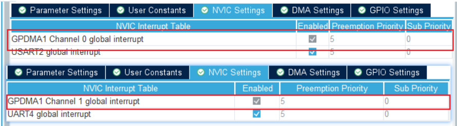
First use STM32CubeMX to configure UART2 and UART4, using DMA for both sending and receiving. The configuration is shown below:

Code Call
usaet.c
static SemaphoreHandle_t g_UART2_TX_Semaphore;static uint8_t g_uart2_rx_buf[100];static QueueHandle_t g_xUART2_RX_Queue;
static SemaphoreHandle_t g_UART4_TX_Semaphore;static uint8_t g_uart4_rx_buf[100];static QueueHandle_t g_xUART4_RX_Queue;
void HAL_UART_TxCpltCallback(UART_HandleTypeDef *huart)//This callback function is called after sending is complete{  if (huart == &huart2)  {    xSemaphoreGiveFromISR(g_UART2_TX_Semaphore, NULL);//Release semaphore  }  if (huart == &huart4)  {    xSemaphoreGiveFromISR(g_UART4_TX_Semaphore, NULL);//Release semaphore  }}
void HAL_UART_RxCpltCallback(UART_HandleTypeDef *huart)//This callback function is called after receiving is complete{  if (huart == &huart2)  {    /* write queue : g_uart4_rx_buf 100 bytes ==> queue */    for (int i = 0; i < 100; i++)    {      xQueueSendFromISR(g_xUART2_RX_Queue, (const void *)&g_uart2_rx_buf[i], NULL);    }        /* re-start DMA+IDLE rx */    HAL_UARTEx_ReceiveToIdle_DMA(&huart2, g_uart2_rx_buf, 100);  }      if (huart == &huart4)  {    /* write queue : g_uart4_rx_buf 100 bytes ==> queue */    for (int i = 0; i < 100; i++)    {      xQueueSendFromISR(g_xUART4_RX_Queue, (const void *)&g_uart4_rx_buf[i], NULL);    }        /* re-start DMA+IDLE rx */    HAL_UARTEx_ReceiveToIdle_DMA(&huart4, g_uart4_rx_buf, 100);  }}
void HAL_UARTEx_RxEventCallback(UART_HandleTypeDef *huart, uint16_t Size){  if (huart == &huart2)  {    /* write queue : g_uart4_rx_buf Size bytes ==> queue */    for (int i = 0; i < Size; i++)//If less than 100 data is sent, Size bytes are received    {      xQueueSendFromISR(g_xUART2_RX_Queue, (const void *)&g_uart2_rx_buf[i], NULL);    }        /* re-start DMA+IDLE rx */    HAL_UARTEx_ReceiveToIdle_DMA(&huart2, g_uart2_rx_buf, 100);  }    if (huart == &huart4)  {    /* write queue : g_uart4_rx_buf Size bytes ==> queue */    for (int i = 0; i < Size; i++)//If less than 100 data is sent, Size bytes are received    {      xQueueSendFromISR(g_xUART4_RX_Queue, (const void *)&g_uart4_rx_buf[i], NULL);    }        /* re-start DMA+IDLE rx */    HAL_UARTEx_ReceiveToIdle_DMA(&huart4, g_uart4_rx_buf, 100);//Re-enable next reception  }}
void HAL_UART_ErrorCallback(UART_HandleTypeDef *huart){  if (huart == &huart2)  {    /* re_start DMA+IDLE rx */    HAL_UARTEx_ReceiveToIdle_DMA(&huart2, g_uart2_rx_buf, 100);  }    if (huart == &huart4)  {    /* re_start DMA+IDLE rx */    HAL_UARTEx_ReceiveToIdle_DMA(&huart4, g_uart4_rx_buf, 100);  }}/* uart2 */int UART2_GetData(struct UART_Device *pdev, uint8_t *pData, int timeout){  if (pdPASS == xQueueReceive(g_xUART2_RX_Queue, pData, timeout))//Read from queue    return 0;  else    return -1;}
int UART2_Rx_Start(struct UART_Device *pDev, int baud, char parity, int data_bit, int stop_bit){  if (!g_xUART2_RX_Queue)  {    g_xUART2_RX_Queue = xQueueCreate(200, 1);//Parameters: create queue length, each data size    g_UART2_TX_Semaphore = xSemaphoreCreateBinary( );//Create a binary semaphore        HAL_UARTEx_ReceiveToIdle_DMA(&huart2, g_uart2_rx_buf, 100);  }  return 0;}
int UART2_Send(struct UART_Device *pDev, uint8_t *datas, uint32_t len, int timeout){  HAL_UART_Transmit_DMA(&huart2, datas, len);//After transmission is complete, the transmission complete interrupt callback function will be called    /* Wait to obtain a semaphore (why not use a mutex? Because releasing a mutex in an interrupt will cause an error) */  if (pdTRUE == xSemaphoreTake(g_UART2_TX_Semaphore, timeout))//If the semaphore is obtained, it means data transmission is complete (similar to a wait function)    return 0;  else    return -1;}
/**/
int UART4_GetData(struct UART_Device *pDev, uint8_t *pData, int timeout){  if (xQueueReceive(g_xUART4_RX_Queue, pData, timeout) == pdPASS)//Read from queue    return 0;  else    return -1;}
int UART4_Rx_Start(struct UART_Device *pDev, int baud, char parity, int data_bit, int stop_bit){  if (!g_xUART4_RX_Queue)  {    g_xUART4_RX_Queue = xQueueCreate(200, 1);//Parameters: create queue length, each data size    g_UART4_TX_Semaphore = xSemaphoreCreateBinary( );//Create a binary semaphore        HAL_UARTEx_ReceiveToIdle_DMA(&huart4, g_uart4_rx_buf, 100);  }  return 0;}
int UART4_Send(struct UART_Device *pDev, uint8_t *datas, uint32_t len, int timeout){  HAL_UART_Transmit_DMA(&huart4, datas, len);    /* Wait for a semaphore (why not use a mutex? Because releasing a mutex in an interrupt will cause an error) */  if (pdTRUE == xSemaphoreTake(g_UART4_TX_Semaphore, timeout))//If the semaphore is obtained, it means data transmission is complete (similar to a wait function)    return 0;  else    return -1;}
struct UART_Device g_uart2_dev = {"uart2", UART2_Rx_Start, UART2_Send, UART2_GetData};//Device name, initialization, sending data, obtaining data
struct UART_Device g_uart4_dev = {"uart4", UART4_Rx_Start, UART4_Send, UART4_GetData};
uart_device.c
#include <stdio.h>#include <string.h>#include "uart_device.h"
extern struct UART_Device g_uart2_dev;extern struct UART_Device g_uart4_dev;
static struct UART_Device *g_uart_devices[] = {&g_uart2_dev, &g_uart4_dev};//Structure array
struct UART_Device *GetUARTDevice(char *name){  int i = 0;  for (i = 0; i < sizeof(g_uart_devices)/sizeof(g_uart_devices[0]); i++)//The second item: total length of structure array divided by the first item for the number of arrays  The purpose is to traverse the array  {    if (!strcmp(name, g_uart_devices[i]->name))//When the output name is the same as the name in the array      return g_uart_devices[i];  }  return NULL;}
uart_device.h
#ifndef __UART_DEVICE_H#define __UART_DEVICE_H
#include <stdint.h>
struct UART_Device {  char *name;  int (*Init)( struct UART_Device *pDev, int baud, char parity, int data_bit, int stop_bit);  int (*Send)( struct UART_Device *pDev, uint8_t *datas, uint32_t len, int timeout);  int (*RecvByte)( struct UART_Device *pDev, uint8_t *data, int timeout);};
struct UART_Device *GetUARTDevice(char *name);    #endif
app_freertos.c
extern UART_HandleTypeDef huart4;extern UART_HandleTypeDef huart2;
static void CH1_UART2_TxTaskFunction( void *pvParameters )  {  uint8_t c = 0;  struct UART_Device *pdev = GetUARTDevice("uart2");//Get device name    pdev->Init(pdev, 115200, 'N', 8, 1);//Call the initialization function in the structure    while (1)  {    /* send data */    pdev->Send(pdev, &c, 1, 100);//Call the send function in the structure    vTaskDelay(500);    c++;  }}
static void CH2_UART4_RxTaskFunction( void *pvParameters )  {  uint8_t c = 0;  int cnt = 0;  char buf[100];  int err;  struct UART_Device *pdev = GetUARTDevice("uart4");//Get device name    pdev->Init(pdev, 115200, 'N', 8, 1);//Call the initialization function in the structure    while (1)  {    err = pdev->RecvByte(pdev, &c, 200);//Get the data into c (returns 0 if data is read from the queue)        if (err == 0)        {      sprintf(buf, "Recv Data : 0x%02x, Cnt : %d", c, cnt++);      Draw_String(0, 0, buf, 0x0000ff00, 0);    }    else    {      //HAL_UART_DMAStop(&huart4);    }  }}