Electric water heaters are a very popular household appliance with a high usage rate. Traditional electric water heaters on the market have low control accuracy and poor reliability. As people’s quality of life improves, their requirements for electric water heaters are increasingly leaning towards intelligence and digitization. Currently, the electric water heaters sold on the market are mainly storage-type, which have advantages such as automatic constant temperature, safety, reliability, and ease of operation, making them very popular among users. However, electric water heaters generally face a contradiction: small-capacity electric water heaters have insufficient continuous hot water supply capacity, making it difficult to meet users’ bathing needs; large-capacity electric water heaters have a long preheating time when used in a cold state (often taking several hours), and when users only need a small amount of hot water, a large amount of cold water is also heated, resulting in significant energy waste. To address this, we propose a new design idea: using a semi-partitioned water tank combined with microcontroller intelligent control technology to prioritize rapid local heating of a small amount of cold water, meeting the requirement for quick hot water supply during initial use; utilizing preheating technology for cold water to achieve continuous large supply of hot water after normal use, effectively solving the aforementioned contradictions present in traditional electric water heaters.
(1) Water Tank DesignStorage-type electric water heaters are divided into open and closed types. Early storage-type electric water heaters were mostly open or open-type, with a simple structure and small volume, relying on pressure spraying from a height, resulting in a small water flow but a low price, suitable for families with few people that only use it for bathing. Open-type electric water heaters do not have pressure-bearing performance designed for the inner tank, so they cannot supply water to multiple pipelines, limiting their functionality. Closed electric water heaters have a sealed inner tank, with high water pressure inside, and the inner tank can withstand pressure, allowing for multi-route water supply. Storage-type electric water heaters can automatically maintain temperature and supply hot water even during power outages. Currently, the main type of electric water heater on the domestic market is the closed storage-type electric water heater, which does not require separate installation, does not produce harmful gases, is clean and hygienic, and allows for easy temperature adjustment. The working principle of closed storage-type electric water heaters is very simple; they use an electric heating tube to provide heat to the water once powered on. The inner tank stores hot water and withstands a pressure of 0.6MPa (approximately 6kg/cm²), with insulation on the outer shell. The differences between products are primarily reflected in the heating tubes, which can be immersion-type, directly contacting the water to be heated, or isolation-type. The heating tube is controlled by a temperature controller, which can set the desired temperature and maintain a constant water temperature in the inner tank, adjustable within the range of 50~70℃. Given the various advantages of closed electric water heaters, we decided to choose a closed-type water heater.
The schematic diagram of the water heater we designed is shown in Figure 1. The water heater consists of two tanks, each with a capacity of 40L, totaling 80L, where the lower tank is the main tank and the upper tank is the storage tank, with both tanks insulated externally. When the water heater is filled, the heating tube in the lower tank heats the cold water, and the heating temperature is controlled by the user through an external button, with a settable temperature range of 40~80℃. The heating temperature of the storage tank is a fixed value, and when it reaches 90℃, it automatically switches to insulation mode. The entire water heater has four water pipes: pipe 1 is the outlet pipe, pipes 2 and 4 are inlet pipes, and pipe 3 is the connecting pipe between the main tank and the storage tank. Pipes 2, 3, and 4 are controlled by solenoid valves for opening and closing. When the water heater is in use, outlet pipe 1 and inlet pipe 2 are opened, while pipes 3 and 4 are closed. When the temperature sensor detects that the water temperature in the main tank drops to 50℃, the microcontroller controls the closure of inlet pipe 2, while opening pipes 3 and 4, allowing high-temperature water from the storage tank to enter the main tank, extending the usable time of the water heater. In summer, when the external temperature is high and not much hot water is needed, the power supply to the heating tube in the storage tank can be turned off, isolating the main tank and storage tank through external circuit control. At this time, the main tank becomes an independent water heater, achieving energy-saving effects. The ends of pipes 2, 3, and 4 are specially designed to ensure that cold water and hot water mix sufficiently.
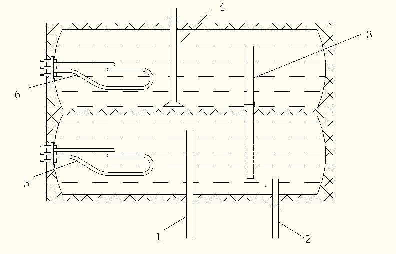
Figure 1: Schematic Diagram of the Water Heater
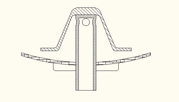
Figure 2: Cross-section of Inlet Components
(2) Software and Hardware Design
First, through analysis, we find that this circuit includes a power supply circuit, heating control circuit, liquid level control circuit, solenoid valve inlet control circuit, button input circuit, LCD display circuit, buzzer alarm circuit, and microcontroller control circuit, etc.
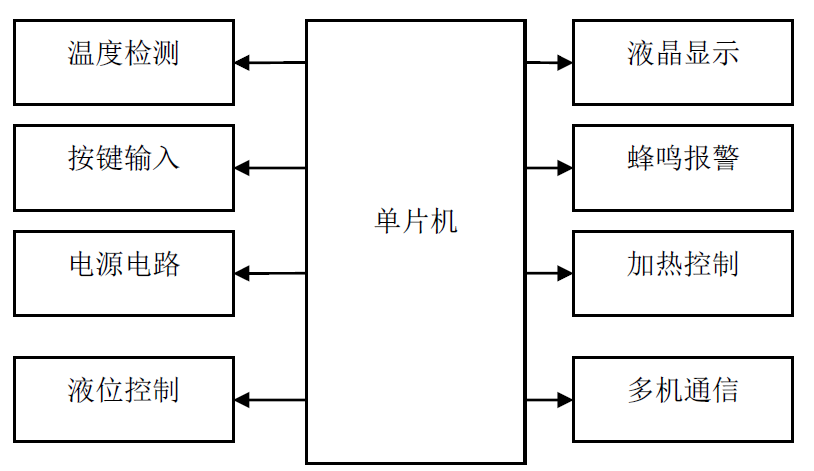
Figure 3: System Design Block Diagram
1. Power Supply Circuit
The power supply circuit uses ordinary 220V AC, which is stepped down and rectified, then stabilized to output +24V voltage through an integrated voltage regulator (7824). The system also requires 12V and 5V voltages, which can be obtained through voltage division. The circuit schematic C5, C6 are input stabilization capacitors, which reduce ripple, dampen, suppress high frequency and pulse interference. C7, C8 are output stabilization capacitors, which improve the transient response of the load. Due to the high ambient temperature around the water heater, when using a three-terminal voltage regulator, the heat sink must be selected according to the output current size; otherwise, it may not work at rated current due to overheating.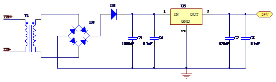 Figure 4: Power Supply Circuit Schematic2. Heating Control Circuit
The heating power of the heating wire is controlled by a bidirectional thyristor. Initially, we chose MOC3023, where the microcontroller triggers the thyristor through an optocoupler, controlling the effective heating power of the heating wire by adjusting the conduction angle of the thyristor. However, adding a zero-cross detection circuit in the circuit to achieve phase delay of the trigger pulse, along with adding interrupt control in the programming, increased the complexity of the hardware and made software programming difficult.
After analysis, we chose to use the optocoupler MOC3041, which has an internal zero-cross detection circuit as the thyristor driver, while also achieving isolation between strong and weak currents. Traditional heating circuits use phase-triggered thyristors to control the conduction angle of the thyristor to control output power, which complicates the synchronous detection circuit and generates high-order harmonic interference at the moment the thyristor conducts, distorting the voltage waveform of the power grid and affecting the normal operation of other electrical devices and communication systems. In this system, we use the ratio of the time of zero-cross triggered thyristor conduction and cutoff to adjust the power of the heating wire, as zero-cross triggering does not change the voltage waveform but only changes the number of times the full wave passes through, thus not polluting the power grid.
At the same time, this system adopts zero-cross triggering. The MOC3041 has an internal zero-cross detection circuit. When input pin 1 receives a current of 15mA, and the voltage between output pins 6 and 4 is slightly over zero, the internal bidirectional thyristor conducts, triggering the external thyristor to conduct. When the input current to pin 1 of the MOC3041 is 0, the internal bidirectional thyristor turns off, thus the external thyristor also turns off. Additionally, R7 and C2 form a surge absorption circuit to prevent surge voltage from damaging the bidirectional thyristor. R6 is the gate resistor of the bidirectional thyristor; when the sensitivity of the thyristor is high, the gate impedance is also high, and R6 can improve the anti-interference capability. R8 is the current-limiting resistor for triggering the bidirectional thyristor.
The relay is connected as a normally closed switch, initially in the heating state, and when the temperature is too high, it cuts off the heating power to achieve over-temperature protection. A diode must be connected in reverse across the relay terminals, as a strong reverse electromotive force will be generated at the moment of power failure, damaging other components. The relay is driven through an optocoupler circuit (TLP521-1 chip) because the relay generates a large current at the moment of rapid opening and closing, which may affect the driving circuit and further impact other circuits on the mainboard. To ensure isolation of the optocoupler system, the power supplies on both sides of the optocoupler must be independent. As shown in Figure 5, the left side of the optocoupler is the microcontroller system with a 5V power supply, while the right side is 12V. If a problem occurs on the right side system, even if the internal transistor of the optocoupler burns out, the left side system will not be affected and can continue to operate normally, which is the benefit of the optocoupler isolation system. The left side of the optocoupler uses components Q7, R13, and R14 to drive the optocoupler, with the main purpose of providing sufficient current for the optocoupler to turn on.
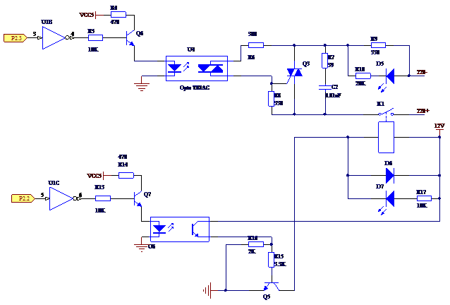
Figure 5: Heating Control Circuit Schematic
3. Solenoid Valve Inlet Control CircuitIn the solenoid valve inlet control circuit, the optocoupler driving circuit is similar to the heating control circuit and does not require further analysis. Pins P1 connect to the solenoid valve, and the right side of the optocoupler circuit is controlled by a MOSFET. When P2.1 inputs a low level, Q1 conducts, and the right side of the optocoupler circuit is in the conducting state. At this time, the upper end of the voltage regulator reaches about 10V, Q2 MOSFET conducts, and the drain terminal is at a low level, activating the solenoid valve; otherwise, it does not work. This circuit also achieves the effect of weak and strong current separation using a MOSFET. Since the solenoid valve is a large inductive device, it generates a large current at the moment of power failure, affecting the normal operation of the driving circuit.
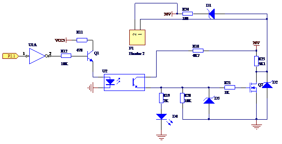
Figure 6: Solenoid Valve Inlet Control Circuit Schematic
4. Liquid Level Control CircuitThe VIN+ pin of the ADC0804 is connected to the output pin of the pressure sensor, which converts the height of the water level into a certain pressure, then converts it into an analog voltage output, which is converted into a digital signal through AD and input into the microcontroller. The microcontroller processes this to obtain the specific liquid level, further controlling the on/off of the solenoid valve.
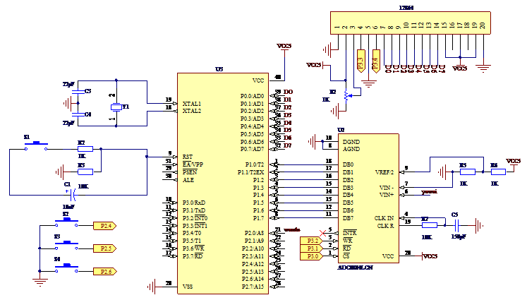
Figure 7: Liquid Level Control Circuit Schematic
5. Temperature Detection Circuit
Selection of Temperature Sensor: After comparison, we chose the DS18B20 temperature sensor. It has advantages such as miniaturization, low power consumption, high performance, strong anti-interference capability, and easy compatibility with microprocessors, allowing direct conversion of temperature into serial digital signals for processing by the processor.
Characteristics of the DS18B20 temperature sensor:1. Wide voltage range, operating voltage range of 3.0~5.5V.2. Temperature measurement range of -55~+125℃, with an accuracy of ±0.5℃ in the range of -10~+85℃.3. Programmable resolution of 9 to 12 bits, corresponding to resolvable temperatures of 0.5℃, 0.25℃, 0.125℃, and 0.0625℃, achieving high precision temperature measurement.4. At 9-bit resolution, it can convert temperature to digital in a maximum of 93.75ms; at 12-bit resolution, it can convert temperature to digital in a maximum of 750ms.5. Measurement results directly output digital temperature signals, transmitted to the CPU via a “one-wire bus”, while also transmitting a CRC check code, providing strong anti-interference error correction capability.
6. LCD Display Circuit
In this system, the 12864 is connected in parallel with the microcontroller, with pin 5 of the 12864 connected directly to low level and pin 15 connected directly to high level to save the I/O ports of the microcontroller.
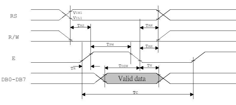
Figure 8: Timing Diagram for Parallel Write Operation of 12864
7. Charging Circuit
During the use of the water heater, to fully utilize the kinetic energy of the water, we install an impeller at the valve, along with a small power DC generator, which can convert the kinetic energy of the water into electrical energy stored in a battery. Additionally, the generator circuit must use a voltage regulation circuit to keep the output voltage constant at a fixed value. Even during a power outage, the microcontroller can use the battery’s electrical energy, allowing some functions to still be operational, such as displaying date, water level, temperature, etc. Of course, this can also be achieved through the microcontroller implementing the function of an intelligent charger. To achieve intelligent charging, the processing and control functions of the microcontroller need to be applied. The implementation of charging is based on the basic charging voltage, controlling the charging process.
The functional modules implemented are as follows:
(a) Microcontroller module for intelligent control of the charger;
(b) Dedicated battery charging chip for controlling the charging process;
(c) Voltage conversion chip to provide charging voltage module.
Common rechargeable batteries include nickel-cadmium, nickel-hydrogen, and lithium-ion rechargeable batteries. Nickel-cadmium and nickel-hydrogen rechargeable batteries should be charged before complete discharge; after several cycles, the battery capacity will decrease, a phenomenon known as memory effect. Lithium batteries do not have memory effect, so even if they are not fully discharged before charging, it will not affect the battery capacity.
Choosing a suitable charging chip for the microcontroller is very important and needs to be based on battery type, current value, charging method, and other criteria.
(1) MAX1898 Chip
After comparison, we chose the MAX1898 as the battery chip to implement a lithium-ion charger, which charges quickly and has strong battery protection capabilities. The MAX1898, in conjunction with external PNP or PMOS transistors, can form a complete charger for a single cell battery. The MAX1898 provides precise constant current/constant voltage charging, with a battery voltage regulation accuracy of ±0.75%, improving battery performance and extending service life.Main functional features of the MAX1898 include:Using low-cost PNP or PMOS adjustment components; simple and safe linear charging method; built-in current sensing resistor, programmable charging current; LED charging status indicator; programmable safety timer; optional/adjustable automatic restart; input voltage range of 4.5~12V, with automatic monitoring of input power supply.(2) LM7805 ChipThis chip converts the voltage to a fixed +5V voltage for the relevant circuits.
(3) 6N137 Chip
To reduce power supply interference and maintain circuit stability, after voltage conversion, it needs to go through an optocoupler module. By controlling the optocoupler module with the microcontroller, the charging power supply can be turned off in a timely manner. The optocoupler module used here is the 6N137 optocoupler.
When the 6N137 optocoupler operates, the signal is input from pins 2 and 3, the light-emitting diode emits light, and the light is transmitted to the photodiode through the internal optical channel. The reverse-biased photodiode conducts after being illuminated, and after current-voltage conversion, it is sent to one input of the AND gate, with the other input being the enable pin. When the enable pin is high, the AND gate outputs high, and after inversion by the output transistor, the optocoupler outputs low. When the input current is less than the trigger threshold or the enable pin is low, it outputs high, but this logic high is open-collector, which can be pulled up with a resistor or voltage adjustment circuit for the receiving circuit.
8. Multi-Machine Communication CircuitThe current issue is how to use two tanks to make the efficiency of the two tanks greater than the total efficiency of two single tanks. Since the function of a single tank is already clear, implementing two tanks is relatively simple. We place the two tanks vertically, with the lower tank referred to as tank 1 and the upper tank as tank 2. First, both tanks automatically fill with water; tank 1 fills close to full, then the solenoid valve b is closed; tank 2 fills completely, then solenoid valve c is closed; during the water filling process, the intermediate solenoid valve a remains closed. The heating power of tank 2 is more than twice that of tank 1, but its capacity is only half that of tank 1. After filling, tank 1 heats to 50℃, and tank 2 heats to 70℃, then both are in insulation mode. When the water level in tank 1 drops, the size of the valve of the intermediate solenoid valve a is adjusted based on the flow rate of the outlet pipe, continuously injecting hot water from tank 2 into tank 1, while adjusting the heating power of tank 2, and the heating power of tank 1 only needs to reach auxiliary heating effect. Of course, two microcontrollers are needed to ensure coordination between the two tanks, which can increase control I/O ports for easier control and improve operational efficiency. To achieve this function, multi-machine communication of microcontrollers is required.Multi-machine systems composed of microcontrollers often adopt a bus-type master-slave structure. The so-called master-slave structure means that among several microcontrollers, one is the master, and the rest are slaves, with slaves needing to obey the scheduling and control of the master. The serial port modes 2 and 3 of the 51 microcontroller are suitable for this master-slave communication structure. Of course, when adopting different communication standards, corresponding level conversion is also required, and sometimes signal opto-isolation is necessary. In practical multi-machine application systems, the RS-485 serial standard is commonly used.During multi-machine communication, the communication protocol must adhere to the following principles:1. All slave machines’ SM2 position 1 is in the receiving address frame state.2. The master sends an address frame, where 8 bits are the address, and the 9th bit is the address/data partition flag, with this position being 1 indicating that the frame is an address frame. After receiving the address frame, all slaves compare the received address with their own address. For slaves with matching addresses, they set their SM2 position 0 (to receive data frames sent randomly by the master) and send their own address back to the master as a response; for slaves with non-matching addresses, they keep SM2=1 and ignore the data frames sent by the master.3. After the slave sends data, it must send a frame effect and set the 9th bit (TB8) to 1 as a flag indicating the end of slave data.4. When the master receives data, it first checks the data reception flag (RB8). If RB8=1, it indicates that data transmission has ended, and it compares the frame effect. If correct, it sends back a correct signal 00H, commanding the slave to reset (i.e., wait for the address frame again); if the effect is incorrect, it sends signal 0FFH, commanding the slave to resend data. If the received frame’s RB8=0, it stores the data in the buffer and prepares to receive the next frame of information.
5. After the master receives the slave’s response address, it confirms whether the address matches. If the address does not match, it sends a reset signal (data frame TB8=1); if the address matches, it clears TB8 to 0 and starts sending data. After receiving the reset command, the slave returns to the listening address state (SM2=1), otherwise, it starts receiving data and commands.
Main Code as Follows:
/////#include"BoardConfig.h"/*LCD interface definition*/////#define RS BIT1/////#define RW BIT2/////#define LCDEN BIT3/*Temperature sensor interface operation macro definition*/#define DQ1 P2OUT |= BIT7#define DQ0 P2OUT &= ~BIT7#define DQ_in P2DIR &= ~BIT7#define DQ_out P2DIR |= BIT7#define DQ_val (P2IN & BIT7)/*Button definitions*/#define KEY_SEL P1SEL#define KEY_IN P1IN#define KEY_OUT P1OUT#define KEY_DIR P1DIR/***********/#define beep_baojing P6OUT^=BIT4/*Define arrays*/unsigned char table0[]="Current Water Temperature: degrees";unsigned char du[]="degrees";unsigned char table1[]="Set Water Temperature: degrees";unsigned char table2[]="Water Level";unsigned char nRes=30;unsigned char temprature[2]={0x00,0x00};//Used to temporarily store two bytes of data read from the temperature sensor/////unsigned char dot_data[16]={0x00,0x01,0x01,0x02,0x03,0x03,0x04,0x04,//Store the encoding of decimal places ///// 0x05,0x06,0x06,0x07,0x08,0x08,0x09,0x09};unsigned char temprature_dis[3]={0,0,0};//Final temperature processing resultunsigned char temprature1[2]={0,0};///////unsigned char mytab[8]={0x0C,0x12,0x12,0x0C,0x00,0x00,0x00,0x00};//Display temperature unit degrees (circle)void delay(unsigned int z)//Normal delay{ unsigned int x,y; for(x=z;--x;) for(y=200;--y);}void delay2(unsigned int a){ while(a--);}/*Below is the temperature sensor operation program*/unsigned char ds18b20_init(void){ unsigned char flag; // DQ_out; _DINT(); DQ0; delay2(500); DQ1; delay2(50); // DQ_in; _NOP(); if(DQ_val) { flag = 1; //Initialization failed } else { flag = 0; //Initialization successful } //DQ_out; DQ1; _EINT(); delay2(400); return flag;}unsigned char read8(void){ unsigned char i; unsigned char temp = 0; _DINT(); for(i = 0;i < 8;i++) { temp >>= 1; DQ0; delay2(5);; //Delay 5us DQ1; delay2(10); //Delay 10us DQ_in; _NOP(); if(DQ_val)temp |= 0x80; delay2(45);; //Delay 45us DQ_out; DQ1; } _EINT(); return temp;}void write8(unsigned char datt){ char i,nBit; for (i=8; i>0; i--) { // DQ_out;// Set pin direction to output DQ0;// Pull DQ pin low nBit = datt & 0x01;// Output data if (nBit) { DQ1; } else { DQ0; } delay2(50);// Delay 50 microseconds DQ1;// Pull DQ pin high datt >>= 1; }}void read_temp(){ ds18b20_init(); write8(0xcc); write8(0x44); //delay(500); ds18b20_init(); write8(0xcc); write8(0xbe); temprature[0]=read8(); temprature[1]=read8();}void deal_int(){ ///// temprature_dis[2]=(((temprature[1]&0x0f)<<4)|((temprature[0]&0xf0)>>4))/100+0x30; temprature_dis[1]=(((temprature[1]&0x0f)<<4)|((temprature[0]&0xf0)>>4))%100/10+0x30; temprature_dis[0]=(((temprature[1]&0x0f)<<4)|((temprature[0]&0xf0)>>4))%100%10/1+0x30; /////if(temprature_dis[2]==0x30)temprature_dis[2]=0x20; if(temprature_dis[1]==0x30)temprature_dis[1]=0x20;}/*void deal_dot(){ temprature_dis[0]=dot_data[temprature[0]&0x0f]+0x30;}*/ /*Below is the 12864 LCD program*/void lcd12864_write(unsigned char flag,unsigned char dat){ if(flag==1) { P3OUT |=BIT1; } else if(flag==0) { P3OUT&=~BIT1; } P3OUT&=~BIT2; P4OUT=dat; delay(2); P3OUT |=BIT3; delay(2); P3OUT&=~BIT3;} void lcd_init() { lcd12864_write(0,0x0f); delay(1); lcd12864_write(0,0x30); delay(1); lcd12864_write(0,0x0c); delay(1); lcd12864_write(0,0x01); delay(1);}void keyPress(void){ int nP10; KEY_SEL&=0Xf0;//Set P1.0-P1.3 as normal IO KEY_DIR&=0Xf0;//P1.0 to P1.3 as input KEY_OUT=0X0f;//P1.0 to P1.3 all output high level nP10 = KEY_IN & 0x0f ;//Read the state of P1.0 to P1.3 /////if (nP10 == 0x0e && nRes <80) nRes=nRes+1;//P1.0 key pressed /////if (nP10 == 0x0d && nRes >40) nRes=nRes-1;//P1.1 key pressed /////if (nP10 == 0x0b) nRes = 3;//P1.2 key pressed /////if (nP10 == 0x07) nRes = 4;//P1.3 key pressed if(nP10 != 0x0f) //If a key is pressed { delay(1200); //Delay for debounce if(nP10 != 0x0f) //Check key state again { if (nP10 == 0x0e && nRes <80) nRes=nRes+1;//P1.0 key pressed if (nP10 == 0x0d && nRes >20) nRes=nRes-1;//P1.1 key pressed } delay(2400); }}void lcd12864_dis(){ unsigned char tem; tem=nRes; temprature1[0]=tem/10+0x30; temprature1[1]=tem%10+0x30; lcd12864_write(0,0x95); lcd12864_write(1,temprature1[0]); lcd12864_write(1,temprature1[1]); lcd12864_write(0,0x85); /////lcd12864_write(1,temprature_dis[2]); lcd12864_write(1,temprature_dis[1]); lcd12864_write(1,temprature_dis[0]);}/*Alarm*/void baojing(){ unsigned int n=0; unsigned int t1; t1=(temprature_dis[1]-'0')*10+(temprature_dis[0]-'0'); if(t1>=nRes) { for(n=21;--n;) { beep_baojing; delay(22); } }}int main( void ){ WDTCTL = WDTPW + WDTHOLD;// BoardConfig(0xbe); //***********Configure Clock*************// unsigned int i; BCSCTL1 &= ~XT2OFF; //Turn on XT2 high-frequency crystal oscillator do { IFG1 &= ~OFIFG; //Clear crystal failure flag for (i = 0xff; i > 0; i--); //Wait for 8MHz crystal to oscillate } while ((IFG1 & OFIFG)); //Is the crystal failure flag still present? BCSCTL2 |= SELM_2 + SELS; //Select high-frequency crystal for MCLK and SMCLK TACTL |= TASSEL_2 + ID_3; //Select counting clock SMLK=8MHz, after 1/8 division is 1MHz //***Initialize LCD and temperature sensor ports***// P2DIR|=BIT7;/****************************/ /*Initialize temperature data port to low level*/ P2OUT|=BIT7;/****************************/ P3DIR|= (BIT1+BIT2+BIT3);/****************************/ /*Initialize LCD command port to low level*/ P3OUT&=~(BIT1+BIT2+BIT3);/****************************/ P4DIR|=0XFF; /****************************/ /*Initialize LCD data port to low level*/ P4OUT&=~0XFF;/****************************/ P6DIR|=BIT4;//Initialize buzzer output P6OUT|=BIT4; lcd_init();//Initialize LCD read_temp();//First temperature reading delay(5000); /*12864's first line displays "Current Temp is:"*/ lcd12864_write(0,0x80); i=0; while(table0[i]!='\0') { lcd12864_write(1,table0[i]); i++; } lcd12864_write(0,0x90); i=0; while(table1[i]!='\0') { lcd12864_write(1,table1[i]); i++; } lcd12864_write(0,0x89); i=0; while(table2[i]!='\0') { lcd12864_write(1,table2[i]); i++; } while(1) { keyPress(); read_temp();//read the temperature deal_int();//deal the integer /////deal_dot();//deal the dot baojing(); lcd12864_dis(); delay(200); }}
(3) Conclusion and OutlookFrom the prototype perspective, the product we designed has higher performance, capable of generating more heat in the same time, making it more suitable for collective accommodation groups, such as student dormitories in universities, employee dormitories in companies, and public bathing places, etc.Of course, due to time constraints, there are still some issues in the design process. For example, during water filling, it is necessary to expel air from the tank, and the water in both tanks needs to remain full, which requires designing an exhaust port, and a water level detection device is also needed; for the ratio of the two tanks, a mathematical model needs to be established or experiments conducted to determine the optimal ratio to achieve the best energy-saving effect. We will further improve this in the future.