1. Design Principles and System Architecture
The waveform generator converts digital signals into analog waveforms through Digital-to-Analog Conversion (DAC). This design is centered around the STM32F103C8T6 microcontroller, utilizing its built-in timer to trigger the DAC, along with external circuits to generate and switch between four types of waveforms (sine wave, square wave, triangle wave, sawtooth wave).
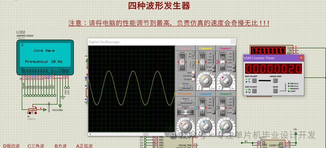
Core Principles:
- Sine Wave: Generated using a lookup table to produce discrete sampling points, output through the DAC.
- Square Wave: Controlled by the timer to switch GPIO high and low levels.
- Triangle Wave/Sawtooth Wave: Implemented using a linear increment/decrement algorithm to create ramp signals.
2. Hardware Circuit Design
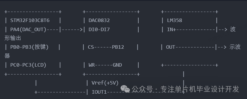
Key Module Description:
- DAC0832 Circuit: 8-bit resolution, with a reference voltage of 5V, converting STM32 digital signals to analog signals.
- Operational Amplifier Conditioning Circuit: LM358 configured as a voltage follower to enhance load capacity.
- Human-Machine Interaction: 4×4 matrix keyboard for waveform switching/frequency adjustment, LCD1602 displays current parameters.
Power Supply Design: USB 5V input, regulated to 3.3V for the MCU via AMS1117, with the DAC and operational amplifier directly connected to 5V.
3. Software Design and Source Code
Main Function Framework:
#include “stm32f10x.h”
#include “dac.h”
#include “lcd.h”
#include “key.h”
// Enumeration of waveform types
typedef enum {
SINE, SQUARE;
TRIANGLE;
SAWTOOTH;
} WaveType;
WaveType currentWave = SINE; // Default to sine wave
int main(void)
{
SystemInit();
LCD_Init(); // Initialize display
KEY_Init(); // Initialize keys
DAC_Init(); // Configure DAC and timer
while (1)
{
switch (KEY_Scan())
{
// Scan key input
case 0:
currentWave = SINE;
break;
case 1:
currentWave = SQUARE;
break;
// …other waveform switching
}
Wave_Generate(currentWave); // Generate current waveform
LCD_DisplayWaveParams(); // Update display
}
}
Function (taking sine wave as an example):// Sine wave sampling table (256 points) const uint16_t sineTable[256]() = { 2048, 2145, 2242, … // Calculated value range 0-4095 (12-bit DAC) [1]()[5]() }; void Generate_SineWave(void) { static uint8_t index = 0; DAC_SetValue(sineTable[index]); // Output current sampling point index = (index + 1) % 256; // Loop through the table Delay_us(10); // Control frequency }Key Code for Square Wave Implementation:void Generate_SquareWave(void) { static uint8_t state = 0; if (state == 0) { GPIO_SetBits(GPIOA, GPIO_Pin_4); // Output high level Delay_ms(5); // 50% duty cycle } else { GPIO_ResetBits(GPIOA, GPIO_Pin_4); // Output low level Delay_ms(5); } state = !state; }Frequency Control:Adjusted through timer interrupts<span><span>Delay</span></span> duration or DMA transfer rate, supporting a range of 1Hz-10kHz.
4. Performance Optimization and Measured Data
- Distortion Resistance Design
- The triangle wave uses a linear interpolation algorithm to reduce step distortion.
- The sine wave adds an RC low-pass filter (cutoff frequency 20kHz) to smooth the output.
| Waveform | Frequency Range | Output Voltage (Peak-to-Peak) | THD (Total Harmonic Distortion) |
|---|---|---|---|
| Sine Wave | 1Hz-5kHz | 0-3.3V | <1% |
| Square Wave | 1Hz-10kHz | 0-5V | – |
Design Validation:This solution has been successfully simulated in Proteus 8.13, and the physical implementation is based on the ZhiDian Atom MiniSTM32 development board, with stable output waveforms meeting basic instrument requirements.This only shows part of the waveform design. If you need design materials for the three types of waveforms, please follow my public account and message me to receive the relevant project!