Common On-Site Embarrassments
The equipment is down, and the screen displays “ERR-047”. The operator looks at the code in confusion and picks up the phone: “The equipment is down, reporting 047.” Engineer: “Where?” “I don’t know.” “Go to station 3 and check the proximity switch.” The operator walks over: “It’s on.” “What’s the pressure gauge reading?” “0.5 MPa.” “Try manually pushing the cylinder…”
After a few minutes of fussing, the problem is resolved, but this process exposes issues in the alarm system design: unclear information, ambiguous location, and lack of guidance for handling. Worse still, for intermittent faults, by the time the engineer arrives on-site, the alarm has disappeared, leaving them to guess based on experience or wait for it to occur again.
This situation is too common in non-standard projects. Equipment failures are inevitable, but the speed of resolution depends on the design level of the alarm system.
The Essence of Alarm Systems
Many people understand alarm systems as “code mapping + text display”; this is just the surface. A true alarm system transforms the anomalies detected by the PLC into actionable guidance that can be understood and executed on-site. The quality of this transformation directly determines maintenance efficiency.
A qualified alarm interface should allow operators to quickly understand three things: what is broken, why it is broken, and how to handle it. Achieving this means the alarm system is adequate.
Logical Coding Rules
Partitioned Classification Coding
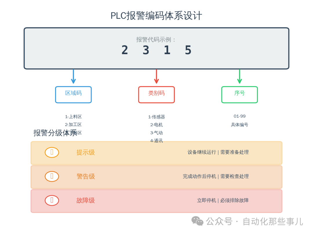
Four-digit structure: the first digit represents the area (1 for loading, 2 for processing, 3 for unloading), the second digit represents the category (1 for sensors, 2 for motors, 3 for pneumatics, 4 for communications), and the last two digits are the sequence number. “2315” indicates the 15th pneumatic fault in the processing area. The benefit of this coding is that hearing the code allows for a rough judgment of the range without needing to flip through manuals.
In the program, use a structure array to manage: code, status, trigger count, first occurrence time, recent time, and cumulative duration. These fields may seem to occupy memory, but each is useful when analyzing problems, especially the trigger count, which can quickly distinguish between sporadic interference and real faults.
Grading Must Reflect Reality
Prompt level (yellow): 20% of raw materials left, time to change oil, equipment can continue running. Warning level (orange): temperature approaching the upper limit, current too high, stop after the current action is completed. Fault level (red): safety door open, servo alarm, immediate shutdown.
The grading standards are based on on-site experience: faults that may damage equipment or cause danger are classified as fault level, those affecting quality or long-term operation are warning level, and auxiliary reminders are prompt level. The goal is to inform the site of priorities rather than a one-size-fits-all shutdown.
Clear Prompt Information
Text Descriptions Must Be Accurate
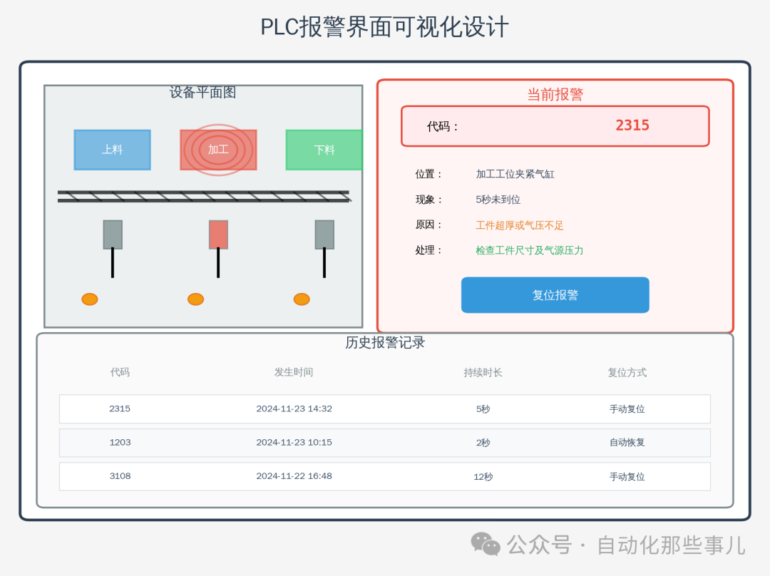
Don’t just write “2315 – cylinder fault”; write “Processing station clamping cylinder has not reached position in 5 seconds – check if the workpiece is too thick or if the air pressure is normal.” Clearly state: location, phenomenon, possible cause, and troubleshooting direction. After reading, the operator can go directly to check without needing to call for confirmation.
These descriptions exist in a program text library, with each code corresponding to a complete explanation. When writing, consider: can a novice take action after reading? If not, it indicates that it is still not clear enough. For export projects, an English version must also be prepared.
Visualization is More Intuitive
Place a floor plan of the equipment on the touchscreen, with alarm locations flashing. Clicking on it displays detailed information: sensor status, valve status, historical counts. A graphical interface is easier to understand than pure text, especially for new employees.
Key locations should have sound and light alarms, with different flashing and sounds for different levels. Operators working next to the equipment can immediately notice when they hear or see it, without having to stare at the screen.
Historical Records are Most Useful
Data Must Be Retained
In the PLC, open a circular buffer to store 500-1000 records: code, occurrence time, disappearance time, duration, reset method. Sync to the touchscreen or upper computer for backup. Even if a temporary alarm disappears, it can still be traced.
This function is most effective for handling intermittent issues. A certain sensor occasionally misreports due to looseness, appearing normal on-site. Checking the records reveals it occurred 15 times in a week, each time for 0.2 seconds, making the problem clear – it was caused by vibration of the mounting bracket. Without historical data, such issues are hard to locate.
Statistics Identify Weak Points
Regularly export alarm statistics sorted by frequency. The top entries indicate weak points in the equipment. A certain photoelectric sensor reported 30 times in a month, indicating either an unreasonable position or quality issues. A certain motor frequently overloads, possibly due to underestimated load calculations or high mechanical resistance.
Statistical data can also guide spare parts management. Knowing what is prone to failure and how often it fails allows for targeted preparation of spare parts, which is more efficient than blind stocking or last-minute purchasing.
Basic Skills to Prevent False Alarms
Signal Confirmation with Delay
Sensors may be interfered with or the measured object may instantaneously fluctuate at the boundary. Directly using the sensor for judgment can easily lead to false alarms. The standard practice is to add a delay: the signal must continuously maintain the fault state for 200-500 ms to be considered a true alarm. This time should be adjusted according to the equipment cycle, with shorter delays for fast equipment and longer for slower ones.
Alarm reset should also have a delay. Wait 300-500 ms after the fault signal disappears before clearing it to avoid repeated triggering at critical points. This delay logic, while simple, can significantly reduce false alarms.
Manage the Masking Function Well
During debugging or manual operation, certain detections need to be temporarily masked. For example, skip sequence detection during single-step debugging, or mask product detection when changing tooling. A masking switch should be provided but must have permissions, and it should automatically restore after exiting debugging. Operators should not be allowed to mask at will, as it can easily leave hidden dangers.
The masking state should be clearly marked, using conspicuous colors to indicate abnormal states. Don’t hide it too deeply; if forgotten, running the equipment with hidden dangers is even more dangerous.
Details Determine Experience
During equipment acceptance, customers do not specifically look at the alarm system. However, after a few months, the differences become apparent: when problems arise, some can be resolved quickly, while others require waiting for remote guidance from engineers. This gap is largely caused by the design level of the alarm system.
A well-designed alarm system can reduce fault handling time by more than half. Common issues can be resolved by operators themselves, maintenance personnel can quickly locate problems based on records, and managers can perform preventive maintenance through statistics. These efficiency improvements ultimately reflect in operating costs and customer evaluations.
The alarm system may seem like just a module in the program, but it is actually the key to the usability of the equipment. Investing more effort during the design phase will significantly improve subsequent maintenance costs and customer satisfaction. The usability of the equipment is reflected in these details.