In PLC programming, it is often necessary to “move this number to that register“, “split a number in half“, “copy a batch of data at once“… These operations are all accomplished through “transfer instructions”.
The transfer instructions in Mitsubishi PLC are like a group of “data porters“: some are skilled at moving single items, some can move in bulk, and some can even “flip” or “split” data. Today, I will explain these instructions one by one, accompanied by examples that beginners can understand, so you can easily handle various data transfer scenarios!
First, understand the “core task” of transfer instructions—moving data
Regardless of the type of transfer instruction, the core is to “move data from one place to another“. Just like in life:
Put 100 yuan from your wallet into a piggy bank (single transfer);
Put a stack of money (10 ten-yuan notes) into a drawer (bulk transfer);
Exchange a 100 yuan note for two 50 yuan notes (split transfer);
In PLC, the “places” are registers (D), constants (K/H), counters (C), etc., and the data can be numbers, switch states, or even a string of binary bits.
1. The most basic “single porter”: MOV instruction (normal transfer)
Function: Move a data “as is” to the target location, overwriting the original data.
Format: MOV source_data target_location
(Source data can be K constants, D registers, C counters, etc.; target location is usually a D register)
Example 1: Store a constant in a register
MOV K123 D10
→ Store decimal 123 in D10, overwriting the original value of D10.
Example 2: Copy data from one register
MOV D20 D30
→ Copy the number in D20 (e.g., 500) to D30, leaving D20 unchanged, and D30 becomes 500.
Example 3: Use the value of a counter to control output
MOV C0 D40
→ Store the current value of counter C0 (e.g., 25) in D40, making it convenient for subsequent comparisons (e.g., when D40 ≥ 30, an alarm is triggered).
2. The “flipping” porter: CML instruction (inverted transfer)
Function: Invert the binary bits of the source data (0 becomes 1, 1 becomes 0), then transfer to the target location (equivalent to taking a “reverse photo” of the data).
Format: CML source_data target_location
Why use it?
For example, if the signal output from a sensor is “active low” (0 indicates a signal), but the PLC conventionally uses 1 to indicate active, CML can be used to invert it.
Example: Invert the number in D10 and store it in D11
Assuming D10’s binary is 0000 0000 0000 0101 (decimal 5),
After executing CML D10 D11,
D11’s binary becomes 1111 1111 1111 1010 (decimal -6, 16-bit signed number).
3. The porter that can “split/merge”: MOVB, MOVD (bit transfer)
Sometimes it is necessary to split a 16-bit number (WORD) into two 8-bit numbers (BYTE), or vice versa; this is when the “bit transfer” instructions are used.
1. MOVB (byte transfer): Move 8-bit data (1 byte)
Format: MOVB source_data target_location
→ Only take the low 8 bits of the source data and transfer them to the low 8 bits of the target (the high 8 bits remain unchanged).
Example: Store the low 8 bits of D20 in the low 8 bits of D21
D20 is 1010 1100 0011 0101 (binary),
After executing MOVB D20 D21:
D21’s low 8 bits become 0011 0101 (the high 8 bits remain unchanged).
2. MOVD (double word transfer): Move 32-bit data (2 words)
Format: MOVD source_data target_location
→ Move two consecutive registers (e.g., D0 and D1 form a 32-bit number) as a whole to the target (e.g., D2 and D3).
Example: Merge D0 and D1, transfer to D2 and D3
D0=low 16 bits (1234), D1=high 16 bits (5678),
After executing MOVD D0 D2:
D2=1234 (low 16 bits), D3=5678 (high 16 bits), completely consistent with D0 and D1.
4. The “bulk mover”: FMOV (bulk transfer)
Function: Transfer a data simultaneously to “a string of consecutive registers” (e.g., store 100 in D10~D15 all at once).
Format: FMOV source_data starting_target quantity
When to use?
To initialize multiple registers (e.g., clear D10~D14 at startup), set a batch of identical parameters (e.g., multiple sensors with the same alarm threshold of 50).
Example: Store 0 in registers D10 to D14
FMOV K0 D10 K5
→ K0 is the data to be transferred, D10 is the starting position, K5 is the quantity (D10, D11, D12, D13, D14), after execution, all five registers become 0.
5. The “swapping” porter: XCH (data exchange)
Function: Swap the data in two registers (like swapping the water in two cups).
Format: XCH register1 register2
Example: Swap the data in D30 and D40
D30=200, D40=500,
After executing XCH D30 D40,
D30=500, D40=200 (data swapped).
Application scenario:
For example, if two silos A and B need to exchange their current inventory levels, XCH can accomplish this in one step without using temporary registers.
6. The “high-low flip” porter: SWAP (high-low byte exchange)
Function: Swap the “high 8 bits” and “low 8 bits” of a 16-bit register (e.g., change “12 34” to “34 12”).
Format: SWAP register
Some sensor output data has “high byte first, low byte last”, but PLC conventionally has “low byte first”; SWAP can be used to flip it.
Example: Flip the high and low 8 bits of D50
D50’s binary is 1100 1010 0011 0111 (high 8 bits: 11001010, low 8 bits: 00110111),
After executing SWAP D50,
D50 becomes 0011 0111 1100 1010 (high and low 8 bits swapped).
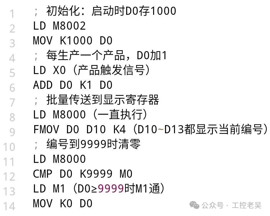
Practical application: Using transfer instructions for “product number management”
Scenario: On the production line, each product has a number (e.g., 1001, 1002…), and it is necessary to:
1. At startup, store the initial number 1000 in D0;
2. For each product produced (triggered by X0), increment D0 by 1 (using the ADD instruction);
3. Simultaneously display the current number on the touchscreen in D10~D13 (using FMOV for bulk transfer);
4. When the number reaches 9999, clear D0 (using MOV K0 D0).
Core program snippet:
Three points for beginners using transfer instructions
1. Do not transfer “incompatible” data: For example, transferring a 32-bit double word to a 16-bit register will result in data loss (use MOVD instead of MOV).
2. Pay attention to the “quantity” in bulk transfers: FMOV K10 D20 K5 will overwrite D20~D24; do not let the quantity exceed the register range (e.g., do not transfer to special registers beyond D8000).
3. It is normal for inverted and flipped data to “look strange”: For example, after CML, a negative number may appear; after SWAP, the number changes; this is because the binary bits have changed, just use them as needed.
Summary: How to choose transfer instructions?
|
Requirement |
Which instruction to choose? |
|
Single data transfer as is |
MOV |
|
Data binary inversion |
CML |
|
Split into bytes or merge double words |
MOVB, MOVD |
|
Bulk transfer of identical data |
FMOV |
|
Exchange two data |
XCH |
|
High-low byte exchange |
SWAP |
These instructions are like wrenches and screwdrivers in a toolbox, each with its own use; once mastered, they can be flexibly combined to easily handle various data transfer scenarios.
Which transfer instruction have you used in your projects? Have you encountered situations where “data was transferred incorrectly”? Share your experiences in the comments! 😉