Abstract:Monitoring and security in areas such as homes, laboratories, offices, factories, and airports are crucial for preventing any threats to human life. Mobile robots have proven effective in numerous applications, especially in hazardous areas, where they can be remotely controlled by humans to perform specific tasks. This research paper presents the design and implementation of a mobile robot for monitoring and security applications. The main goal of this design is to reduce the cost and power consumption of the mobile robot, achieved through the use of low-cost open-source hardware such as Arduino and Raspberry Pi. The robot connects wirelessly to a control station via a low-power ZigBee module, allowing the operator to control the movement of the mobile robot and monitor physical events in the robot’s environment. The robot is embedded with sensors such as cameras, temperature, and distance sensors to perceive and monitor human movement, room temperature, and the distance to surrounding obstacles. Tests conducted on the implemented mobile robot indicate that it can operate continuously for about 6.5 hours at a motor shaft speed of 25 revolutions per minute without needing to recharge the battery.
Original Authors: Abdulkareem Sh. Mahdi Al-Obaidi, Arif Al-Qassar, Ahmed R. Nasser, Ahmed Alkhayyat, Amjad J. Humaidi, Ibraheem K. Ibraheem
Editor: AutoGo

01
Introduction
In practice, robots are electromechanical systems equipped with sensors for controlling their environment, processing information from these sensors, and generating results through actuators that convey the processed results to outputs. Robots can be divided into mobile and non-mobile robots. If a robot’s workspace does not move relative to a reference coordinate system, it is termed a non-mobile robot; if it moves, it is called a mobile robot.
Mobile robots can be utilized in various fields, such as the cleanup of toxic and nuclear waste, explosive ordnance disposal, transportation of biological waste, service robots in isolated environments, cleaning windows of high-rise buildings, mine detection and clearance, construction of space stations, underwater search and rescue, personnel rescue during earthquakes, and parts transportation on factory production lines. Another significant application area for mobile robots is monitoring and security in indoor environments, such as warehouses, airports, and manufacturing plants. In such applications, mobile robots can interact with humans and other robots to monitor the environment and trigger alarms in the event of abnormal occurrences.
The purpose of this paper is to design and implement an affordable and user-friendly wireless-controlled embedded mobile robot suitable for remote monitoring and security applications. The structure of this paper is as follows: Section 2 provides a brief literature review of mobile robots and their applications. Section 3 describes the proposed mobile robot design from both hardware and software perspectives. Section 4 includes the test results of the robot and conclusions.
02
Literature Review
There are numerous studies in the literature regarding the design of mobile robots for different applications, summarized as follows.
Raj et al. discussed safety precautions in fire incidents in areas such as laboratories, homes, offices, factories, and buildings. They emphasized that these places may contain explosive or flammable materials that could lead to fire incidents, and that safety measures can prevent these accidents. Robots are considered one of the best and most effective methods for implementing these safety measures. Therefore, they developed a rescue robot that uses camera sensors and image processing to detect fires.
Liu et al. studied the improvement of error rates in data from multiple sensors in a multi-mobile robot patrolling observation system in a simulated environment. These robots are interconnected wirelessly. They used different combinations of laser, ultrasonic, and camera sensors to collect data from an environment simulated using Microsoft Robotics Developer Studio.
In the research conducted by Nasrinahar et al., obstacle avoidance methods for mobile robots in hazardous areas inaccessible to humans were considered. In these areas, robots can move easily and perform any tasks by reaching the desired location without colliding with any obstacles in the area. Search algorithms were considered to find the optimal path for mobile robots to navigate the environment without hitting obstacles.
Boufera et al. proposed a hybrid method with fuzzy logic to overcome obstacles in uncertain environments for mobile robots. A basic limit conversion method was developed to achieve safe and flexible navigation. By reducing the number of directional changes during the obstacle avoidance process, the avoidance can be made more flexible. The proposed algorithm has been successfully tested in simulations with different configurations.
López et al. proposed an open-source, low-cost (35 euros), modular, and scalable mobile robot. The robot was designed using open-source devices and software based on Android and Arduino. This mobile robot design is intended for remote education and massive open online courses as an alternative to traditional visual laboratories, usable in classroom or laboratory environments.
Ibari et al. designed different algorithms for mobile robot navigation systems. Some algorithms utilized fuzzy logic and genetic algorithms. Lightweight remote presentation robots require simpler and more computationally intensive algorithms. To meet this demand, the odometry method was preferred. Obstacle avoidance features were designed to improve this algorithm. A prototype of the mobile robot was created using Arduino UNO, two DC motors, and an ultrasonic sensor.
One of the significant application areas for mobile robots is monitoring and security applications. In Lopez et al., a mobile robot called the Airport Night Surveillance Expert Robot (ANSER) was designed for monitoring applications in civil airports and similar vast areas. This robot can be controlled by human operators at fixed monitoring stations to monitor activities and events in these areas.
Trovato et al. designed a mobile security robot and implemented it for remote indoor security applications. This robot is used to patrol environments and monitor valuable items, identify individuals, and provide detailed analysis of captured data to the operator.
Another example of a security robot is called MARVIN (Mobile Autonomous Robot Vehicle for Indoor Navigation), designed as an indoor security agent. This robot is equipped with speech synthesis and recognition capabilities and conveys emotional states to interact with humans.
Following this trend in mobile robot applications, this paper designs a low-cost, low-power wireless-controlled mobile robot for monitoring and security applications.
03
Mobile Robot Design
The proposed mobile robot design is divided into two parts. The first part covers the hardware design of the robot, while the second part covers the software development for controlling the robot.
3.1 Hardware Design
The hardware used for designing the mobile robot consists of the following components:
Robot drive unit, ZigBee wireless module, sensors, camera module, microcomputer, and microcontroller (Raspberry Pi and Arduino), as well as a personal computer. Details of each part used in the design of the mobile robot are described below.
3.1.1 Robot Drive Unit
The robot drive unit is responsible for the movement of the robot along the x-axis and y-axis. The robot consists of four wheels to assist in maneuvering on inclined and flat terrain. Each wheel is independently driven by its own DC motor, which is used to control the direction of the robot’s movement, as shown in Figure 1. The speed and rotation direction of each 12-volt DC motor are controlled by the L293D motor driver integrated circuit. The maximum speed of each motor is 95 revolutions per minute.

Figure 1. The movement direction of the robot based on the motor movement of each wheel
3.1.2 Arduino Microcontroller
Arduino is a physical programming platform consisting of I/O boards and a development environment, which includes an implementation of the Processing/Wiring language. Arduino can be used to develop standalone interactive objects or can be connected to software running on a computer (such as Macromedia Flash, Processing, Max/MSP, Pure Data, SuperCollider). Ready-made boards can be purchased, or hardware design information is provided for those who wish to produce their own.
In terms of hardware, Arduino boards consist of Atmel AVR microcontrollers (ATmega8 or ATmega168 in older boards, ATmega328 in newer boards) and side components required for programming and connecting to other circuits. Each board has at least one 5-volt voltage regulator integrated circuit and a 16 MHz crystal oscillator. Since a bootloader is pre-written into the microcontroller, programming does not require an external programmer.
In terms of software, the Arduino IDE is an application written in Java that serves as a code editor and compiler, and it can load the compiled program onto the board, working on any platform. This development environment is based on the Processing software developed to introduce programming to artists.
In the context of the robot design in this work, the Arduino microcontroller is used to retrieve movement commands sent by the operator and convert them into signals for driving the robot’s motors. Figure 2 shows a schematic of using Arduino to drive the robot motors.
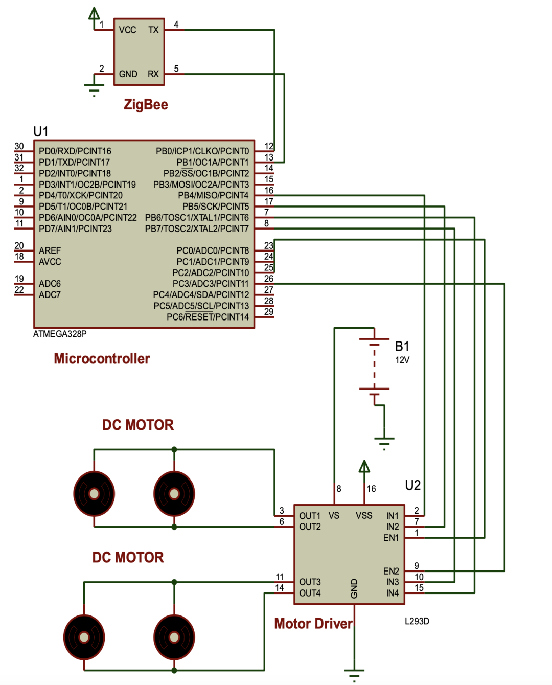
Figure 2. Driving the motors using the microcontroller
3.1.3 Sensors
Sensor electronics are used to convert physical quantities into signals that can be read by instruments or monitoring devices. Two sensors are used in the current design. The first sensor is an ultrasonic sensor, as described below. In the classification of sound waves, sound signals in the range of 20 kHz to 1 GHz are defined as ultrasonic. Many ultrasonic sensors generate ultrasonic waves at a frequency of 40 kHz. An important factor here is the frequency that determines the loudness of the sound. If the sound is high, the frequency is louder. The human ear cannot detect ultrasonic signals. The transducer emits ultrasonic pulses. The pulse is reflected from the deflection and received by the transducer. The propagation time of the pulse is proportional to the distance from the deflection to the sensor. This sensor is used to detect the distance between the robot and obstacles ahead.
The second sensor is a temperature sensor, as described below. The temperature sensor (DS18B20) is a digital sensor with a one-wire interface and a 64-bit serial code. It can measure temperatures from -55°C to +125°C with a resolution of 9 to 12 bits. The maximum measurement and conversion time for 12 bits is 750 milliseconds. It is used for fire detection in the robot’s movement area.
3.1.4 Raspberry Pi Microcomputer
The Raspberry Pi board used in this design is a credit card-sized computer developed by the Raspberry Pi Foundation in the UK for teaching computer science in schools. The Raspberry Pi is primarily used for embedded system applications and applications requiring an operating system, as it can be developed independently of a computer and is easy to use in portable systems. The Raspberry Pi is released in various models with some hardware changes.
The B+ model of the Raspberry Pi board, whose hardware unit is based on the Broadcom BCM2835 SoC (System on Chip), runs a single-core ARM1176JZ-F 700 MHz processor unit with ARMv6 architecture. With the VideoCore IV graphics processing unit in the Broadcom BCM2835 SoC and this 512 MB RAM Raspberry Pi card, most operations can be performed on a regular computer, including high-resolution video playback. The board does not have an internal hard drive to install an operating system; data can be stored on the board, and it can be used as a mini-computer by connecting a keyboard, mouse, and display. For this purpose, an operating system can be installed on the storage card after inserting it into the microSD card slot on the board, and the required data storage operations can be performed. The Raspberry Pi B+ model cannot run the Windows operating system due to its ARMv6 architecture. Therefore, a Linux operating system designed for the Raspberry Pi should be downloaded from the manufacturer’s foundation website and installed on the storage card. Linux operating systems such as Raspbian (based on Debian Wheezy) and Pidora (based on Fedora) are available on the foundation’s website.
In the robot design, the Raspberry Pi serves as the main processing unit connecting the robot’s sensors, as shown in Figure 3. The Raspberry Pi also interfaces with the ZigBee wireless module to provide communication between the robot and the control device. Additionally, a camera module with a resolution of 5 megapixels is designed to connect directly to the CSI connector on the Raspberry Pi board to capture real-time video of the environment and stream it to the control device.
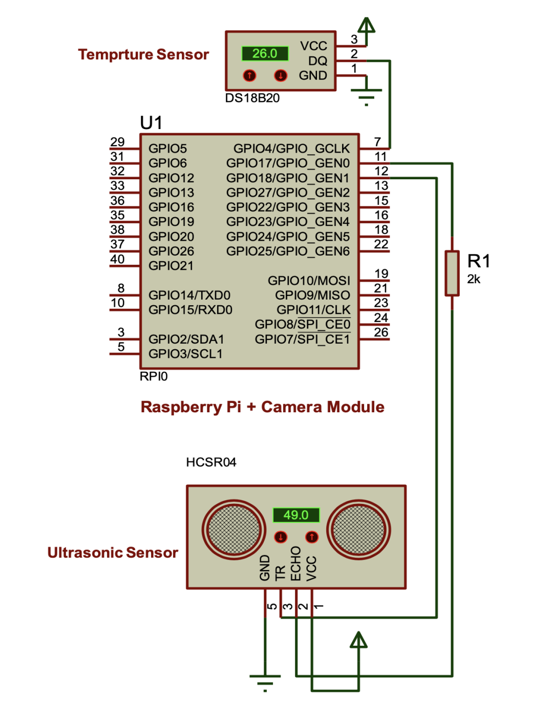
Figure 3. Raspberry Pi connecting temperature and ultrasonic sensors
3.1.5 Wireless ZigBee
The ZigBee network consists of a wireless short-range communication protocol based on the IEEE 802.15.4 standard, providing low-speed data communication. ZigBee is named after the complex zigzag movement that bees make while moving between flowers. This zigzag structure symbolizes communication between nodes in a communication network. The organization that forms ZigBee, called the ZigBee Alliance, is an association of global technology companies, including Philips, Motorola, and Intel. ZigBee-based wireless devices operate at frequencies of 868 MHz, 915 MHz, and 2.4 GHz. The maximum achievable data rate is 250 kilobytes per second. ZigBee is typically targeted at battery applications based on low speed, low cost, and long battery life. In many applications, the activity of ZigBee devices is very limited. Devices usually operate in low-power mode, also known as sleep mode. Therefore, ZigBee devices can work for years without needing to replace batteries.
Due to the advantages of low power consumption, wide range, and speed, ZigBee is used to provide remote control and monitoring capabilities for the robot design. Figure 4 shows a block diagram of wireless communication using ZigBee for the robot and control device.
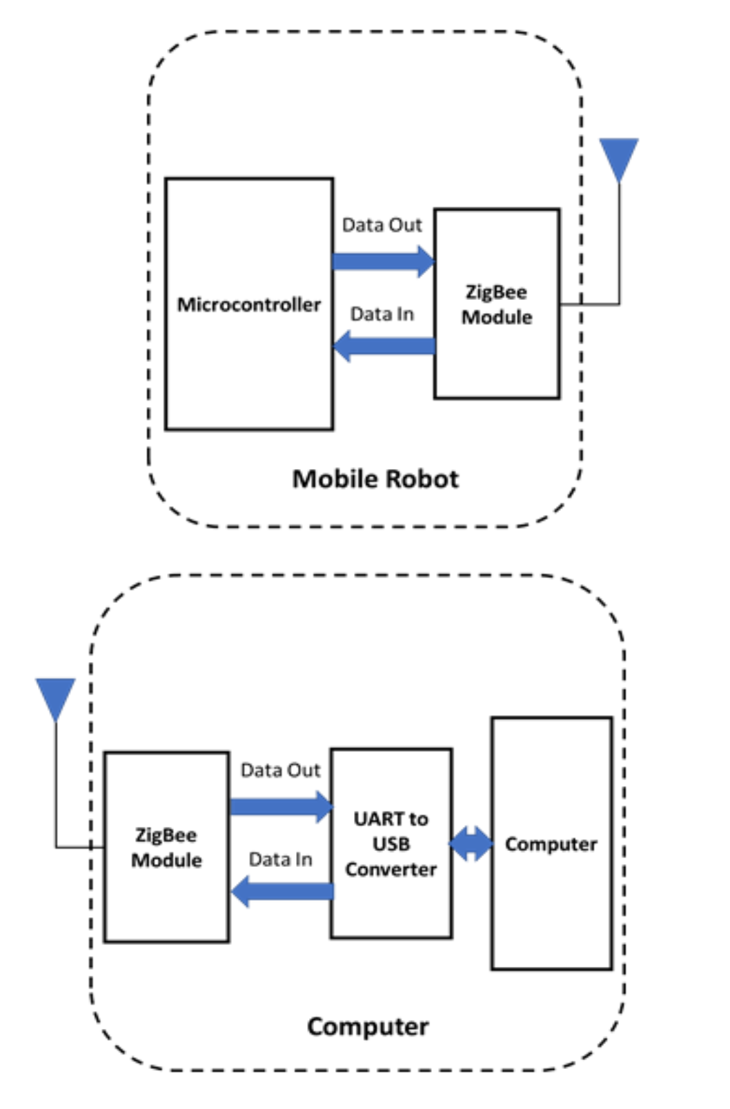
Figure 4. ZigBee wireless communication for the robot and control device
The overall block diagram of the mobile robot design based on the ATmega328 microcontroller and Raspberry Pi is shown in Figure 5.
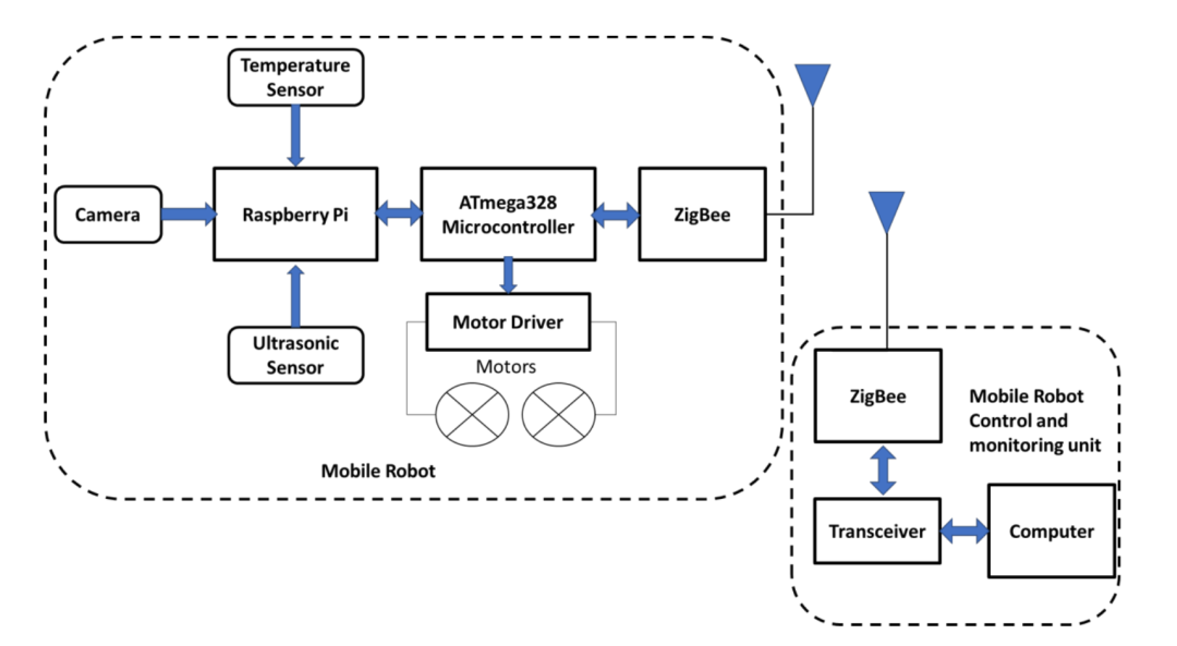
Figure 5. Overall block diagram of the robot design
The operation of each part used in the mobile robot design is described as follows:
· The robot monitors temperature and ultrasonic sensors, and once any anomalies are detected, the robot sends an alert signal from the Raspberry Pi to the main control computer.
· The Raspberry Pi captures video from the camera and streams it to the main control computer, allowing the operator to monitor the environment.
· At the remote end (personal computer), the control software allows the operator to enable or disable the motors on the robot by sending a set of commands, thus controlling the movement of the robot.
· At the remote end (personal computer), the control software allows the operator to monitor the environment through real-time video received from the robot’s camera.
· Communication between the robot and the control and monitoring devices is established via ZigBee wireless.
3.2 Robot Software Development
The software used to control the robot is divided into two parts: robot-side software and remote controller-side software.
3.2.1 Robot-side Software
The robot-side software is responsible for the following tasks:
· Reading the sensor values connected to the robot and reporting them to the control software on the operator’s side.
· Capturing real-time video of the environment from the camera mounted on the robot and streaming it to the monitoring software on the operator’s side.
· Receiving movement commands from the control software on the operator’s side and converting them into movements for the robot’s motors.
The flowchart of the robot-side software is shown in Figure 6.
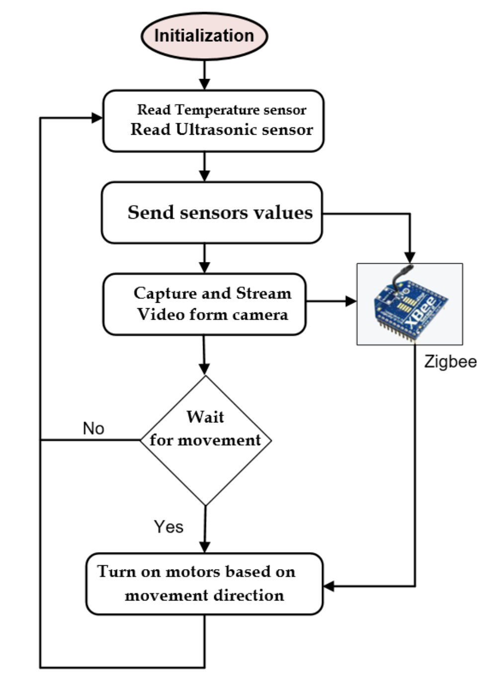
Figure 6. Flowchart of the internal software of the robot
3.2.2 Controller-side Software
The controller-side software is responsible for the following tasks:
· Receiving the sensor values obtained by the robot and displaying them to the operator.
· Receiving real-time video of the environment from the robot and displaying it to the operator.
Sending movement commands to the robot based on the operator’s control, as shown in Figure 7.
The flowchart of the robot-side software is shown in Figure 8.
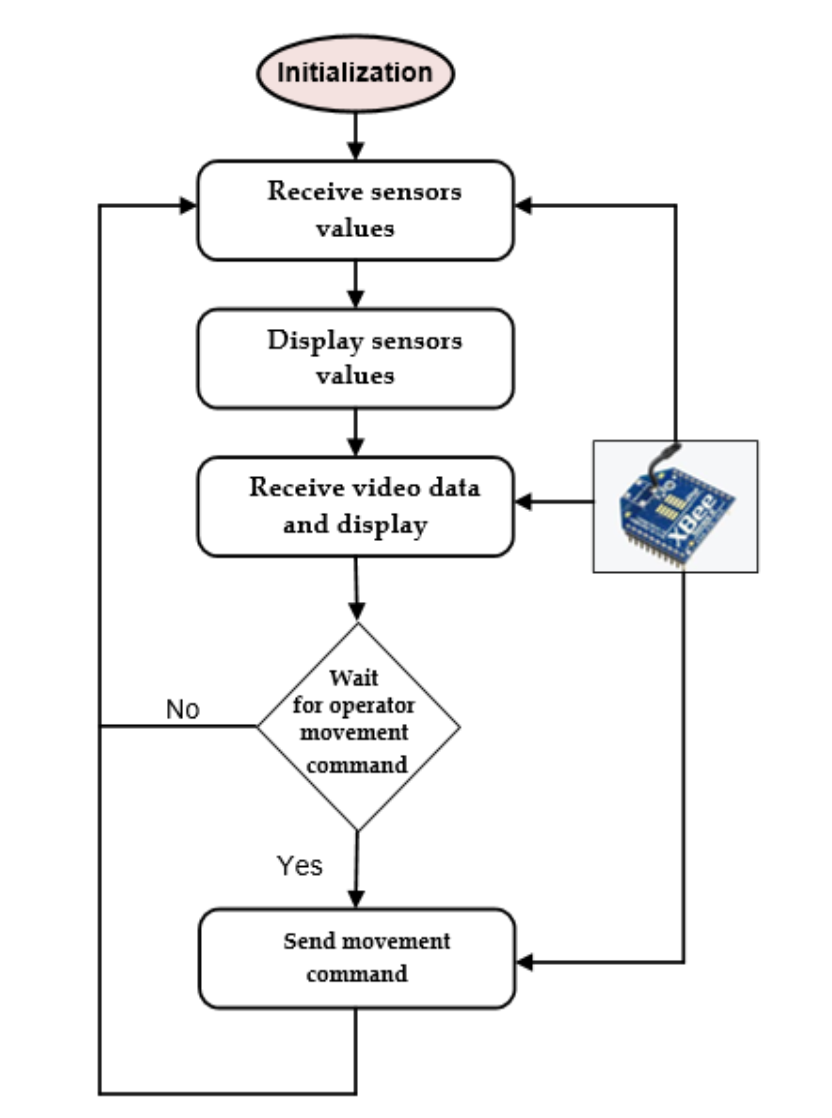
Figure 7. PC-side mobile robot control software
Figure 8. Flowchart of the internal software of the robot control device
04
Results and Conclusions
Based on the design proposed in this research paper, a mobile robot was constructed and implemented. After constructing the mobile robot, practical tests were conducted in the environment. Figure 9 shows the operation of the robot when wirelessly controlled by the operator.
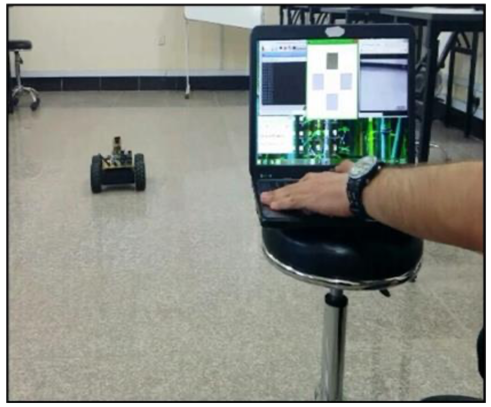
Figure 9. The robot and control operator in action
During testing, the robot was powered by a 12-volt lithium polymer LiPo battery pack with a capacity of 6000 milliamp-hours, and the robot’s operating time was calculated based on the motor shaft speed, as shown in Table 1.
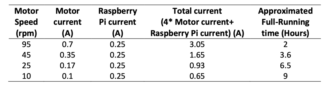
Table 1. Robot operating time based on motor speed
From the test results in Table 1, it can be seen that the mobile robot can operate for a reasonable time at medium and low motor shaft speeds before needing to recharge. The speed of the robot itself can be increased using a gearbox to ensure low power consumption and increase operating time. Note that the current consumption of other components such as sensors and ZigBee is very low, so they were not considered in calculating the total current consumption of the robot. This paper presents the design and implementation of a wireless-controlled mobile robot for security and monitoring applications. The design aims to achieve low cost and power efficiency. This was accomplished by using easily accessible low-cost open-source components and selecting a wireless communication module (ZigBee) with extremely low power consumption. The robot has been partially implemented and tested. This research can be extended to apply advanced control and optimization techniques to enhance the tracking performance of the mobile robot or improve the path planning performance of the mobile robot. Additionally, the navigation of the mobile robot can be developed by incorporating FPGA technology instead of Raspberry Pi.
Disclaimer: The views expressed in this article are for sharing and communication purposes only. The copyright and interpretation rights of the article belong to the original authors and publishing units. If there are any copyright issues, please contact [email protected], and we will address them promptly.
Related Articles ·
▷ Magnetically Controlled Soft Robot Technology
▷ Electronic Skin (E-Skin) — From Humanoid Robots to Humans
▷ A Mass-Produced Social Humanoid Robot – Pepper
▷ The Development History of Quadruped Walking Robots and Various Design and Development Methods
▷ Infineon’s Vice President: Three Key Features to Bring Edge AI Mainstream by 2025
▷ Robustness of Multimodal Fusion in Robots
▷ Honda’s ASIMO and Humanoid Robot Research
▷ The World’s First Bidirectional Adaptive Brain-Computer Interface Developed Successfully by a Chinese Team!
▷ Hardware Design of Biped Humanoid Robots: A Technical Review
▷ Mechanical Principles of Humanoid Robots
▷ Methods of Interaction Between Robots and Humans and Multimodal Interface Architecture
▷ AI-Based Human-Robot Collaborative Unit Task and Action Planning Methods
▷ The Humanoid Robot Market Size Will Reach $76.97 Billion by 2032, with a Compound Annual Growth Rate of 48.36%