Introduction: The previous article was only half written and not published yet, so here’s a quick note.
Preface
Recently, while working with Coresight, I had a persistent question: how does the funnel know which trace source corresponds to the input slave port?
After discussing with the FAE from the chip manufacturer today, I finally understood that the trace source for the Coresight funnel is fixed during hardware design and cannot be set at the software level.
Moreover, the reference manual provided by the chip manufacturer does not describe the source of the funnel, and ultimately, the FAE obtained the mapping relationship of the funnel’s source from the chip IC designers.
This also explains why there was no data in the ETB when I first used CSAL to collect ETM data; after modifying the funnel input port, I was able to successfully collect data.
Coresight Funnel Functionality
The Coresight funnel is a component of the Coresight link, responsible for aggregating data from multiple Coresight trace sources and sending it to the ATB (Advanced Trace Bus).
Below is a typical architecture diagram of a single-core system with ETM and STM as trace sources, which are aggregated by the funnel and transmitted to the next-level replicator (which sends one ATB data to multiple backends).
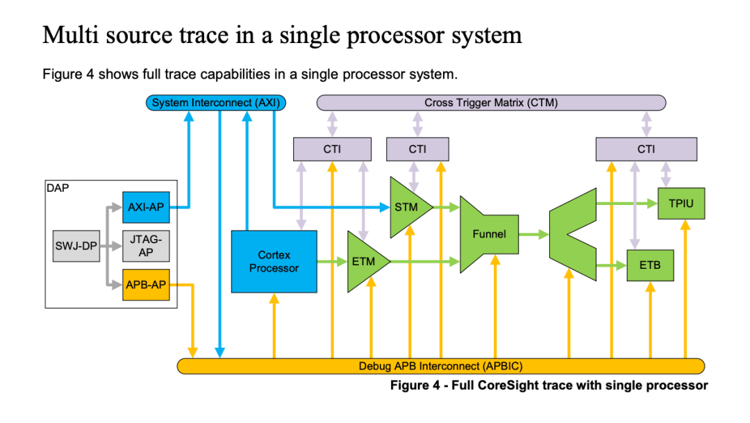
This architecture diagram describes how, in a single-core system, the ETM hardware records CPU instructions, while the STM outputs software data, which is aggregated by the funnel and transmitted to the replicator for sending to the ETB and TPIU.
- ETM (Embedded Trace Macrocells): Embedded trace macro (trace source) that records processor instructions and data.
- STM (System Trace Macrocell): System trace macro (trace source) that can write data to Coresight for processing via software, such as logs or software traces.
- ETB (Embedded Trace Buffer): Embedded trace buffer (trace sink) that stores data from trace sources and can be read via software.
- TPIU (Trace Port Interface Unit): Trace port interface unit (trace sink) that outputs trace source data to the external chip via hardware IO.
Coresight Funnel Register Description
Register Summary
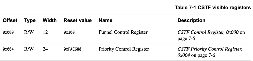
The funnel requires control of only two registers during use: the Control Register and the Priority Control Register, located at addresses 0x00 and 0x04, respectively.
Control Register (0x00)
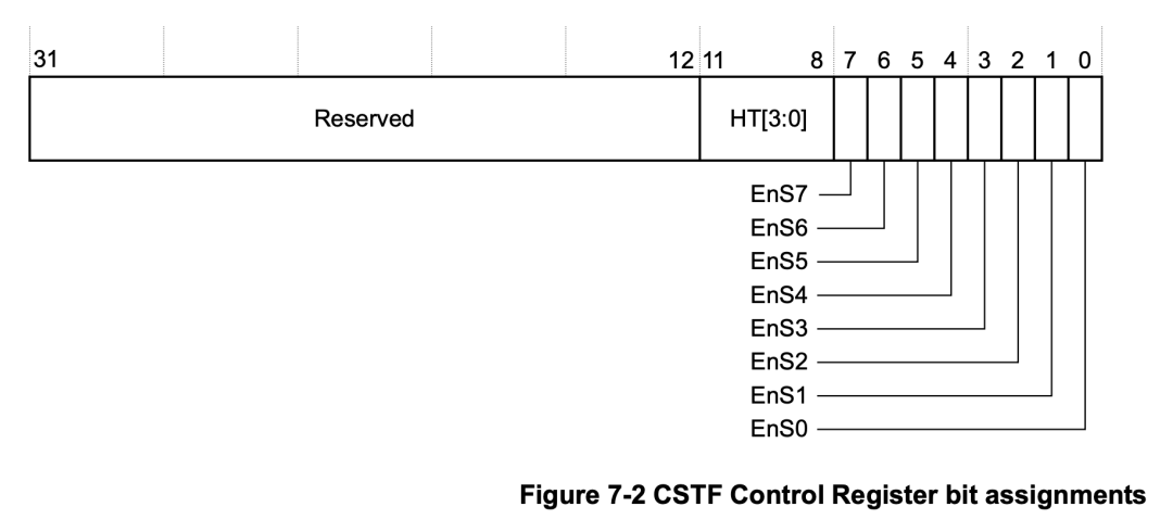
The Control Register is responsible for enabling slave ports and defining the hold time for slave ports.
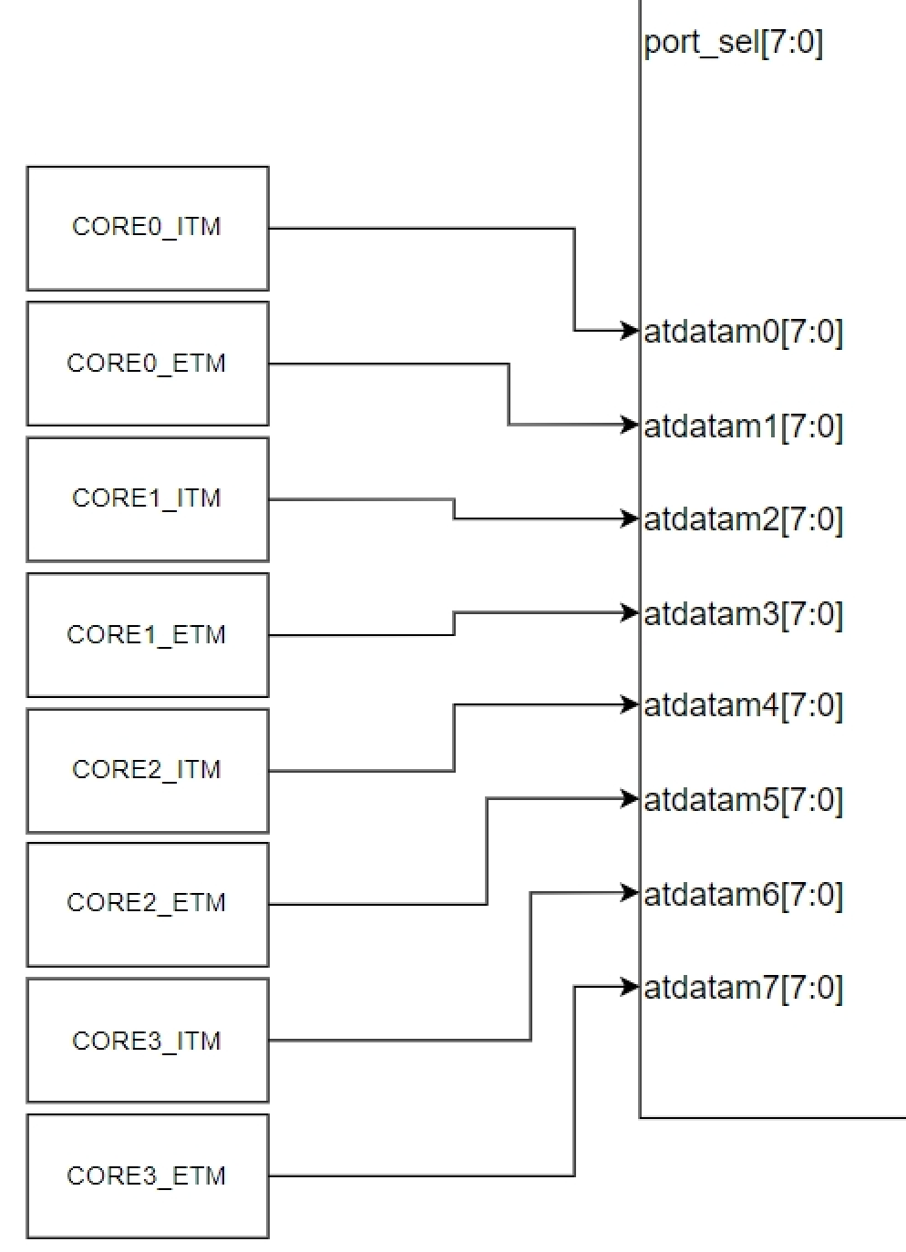
- A funnel supports a maximum of 8 slave ports, each of which can be independently configured via bits 0-7.
- Bits 8-11 define the hold time, which specifies how long the slave port data is held on the ATB bus, with a minimum of 1 clock cycle and a maximum of 15 clock cycles.
- The trace source connected to each slave port in the funnel is fixed and cannot be set at the software level; it can only be enabled or disabled.
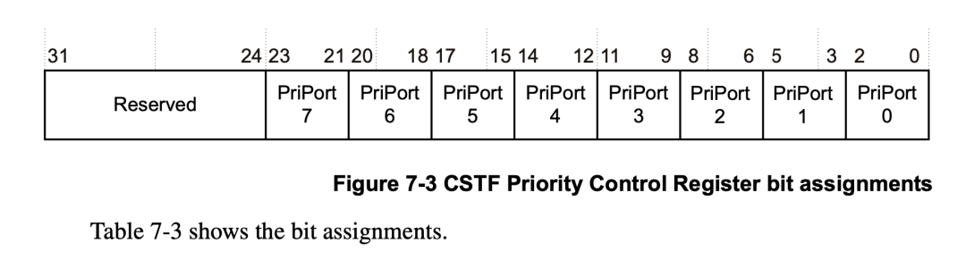
Priority Register (0x04)
The Priority Control Register is used to set the priority of each slave port. When multiple slave ports send data simultaneously, the priority register determines the order of data transmission based on priority.
- Each slave port occupies 3 bits in the priority register, with a selectable range of 0-7; the smaller the priority value, the higher the priority.
- After reset (0xFAC688), the default priority is 0 for port 0 (highest), 1 for port 1, and so on.
- When multiple slave ports have valid data and are enabled, the arbitration logic prioritizes the highest priority port; if multiple ports have the same priority value, the port with the smallest number is selected.
CSAL Code Analysis
After clarifying the above issues, the code in the CSAL library for configuring and enabling trace sources becomes very clear.
// Register STM to funnel's port 0
cs_atb_register(stm, 0, fun_main, 0);
// Register ETM to funnel's input port 1
cs_atb_register(etm, 0, fun_main, 1);
// Register funnel output to ETF's input port
cs_atb_register(fun_main, 0, etf, 0);
In the <span>cs_atb_register</span> function, it seems to bind STM and ETM to the funnel, but it actually only records the topological relationship of each Coresight component.
The actual connection relationship is determined during hardware design, and the <span>_cs_path_enable</span> function is responsible for enabling the trace link devices based on the recorded connections in <span>cs_atb_register</span>.
int cs_atb_register(cs_device_t from, unsigned int from_port,
                    cs_device_t to, unsigned int to_port)
{
    struct cs_device *fd = DEV(from);
    struct cs_device *td = DEV(to);

    // Record the connection between from and to
    fd->outs[from_port] = DEV(to);
    fd->to_in_port[from_port] = to_port;
    td->ins[to_port] = DEV(from);
    td->from_out_port[to_port] = from_port;
    return 0;
}

int _cs_path_enable(struct cs_device *d, int enabled)
{
    unsigned int n;
    int rc = 0;

    // Iterate through from's output ports
    for (n = 0; n < d->n_out_ports; ++n) {
        struct cs_device* od = d->outs[n];
        if (cs_device_is_funnel(od)) {
            unsigned int od_in_port = d->to_in_port[n];
            // If from's output port is a funnel, recursively enable the funnel's output path
            _cs_path_enable(od, enabled);

            // Enable the corresponding port's funnel register
            if (!cs_device_is_non_mmio(od)) {
                _cs_unlock(od);
                rc = _cs_set_mask(od, CS_FUNNEL_CTRL, (1U << od_in_port), (enabled << od_in_port));
                if (rc != 0) {
                    break;
                }
            }
        } else if (cs_device_is_replicator(od)) {
            _cs_path_enable(od, enabled);
        }
    }
    return rc;
}
Conclusion
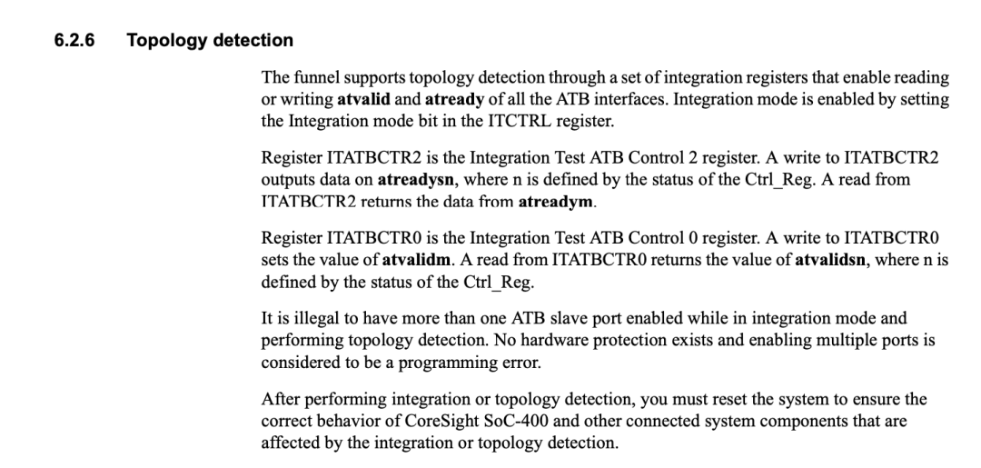
Finally, while writing this article, I revisited the spec and found that the funnel’s integration test registers ITATBCTR0 and ITATBCTR2 can be used for testing.
References
- CoreSight™ Components Technical Reference Manual
- ARM® CoreSight™ SoC-400 Technical Reference Manual
- Arm® CoreSight™ Architecture Specification v3.0
- CoreSight Technical Introduction
end
Love technology, love life
This is an atypical tech enthusiast, click the blue text above to follow
Feel free to click to view👀, like 👍, and save ⭐

WeChat Official Account | Atypical Tech Enthusiast