Sensors are components or devices that convert collected information into signals that can be processed by equipment.
Humans act based on information obtained through vision, hearing, smell, and touch, and devices similarly control or process based on information obtained from sensors.
Sensors collect and convert signals (physical quantities) such as temperature, light, color, atmospheric pressure, magnetic force, speed, acceleration, and more.
These utilize changes in semiconductor materials; in addition, there are biosensors that use biological materials like enzymes and microorganisms.
Not only communication devices like smartphones and personal computers, but also medical devices, wearable devices, automotive, natural environments, and infrastructure can all connect to share information, creating a more convenient, secure, and safe society.
Essential for achieving this is the “sensor” that detects states.
Geomagnetic Sensor
The Earth is surrounded by a magnetic field, known as geomagnetism.
The geomagnetic sensor is a sensor that detects the Earth’s magnetic force, also known as an “electronic compass.”
The geomagnetic sensor can detect direction by detecting geomagnetism.
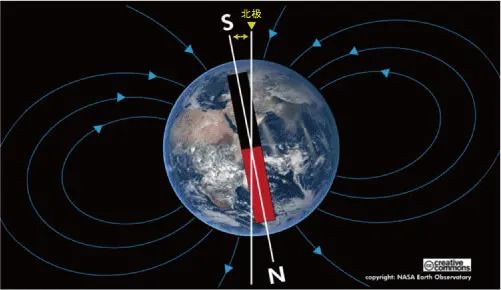
[Geomagnetic Field Surrounding the Earth]
The geomagnetic sensor has X and Y axis types and a three-axis type that adds Z, measuring magnetic force values in each direction.
If we disregard tilting, such as with a simple compass, only the X and Y axis values are used. When considering tilting, it is necessary to combine the three-axis values of the geomagnetic sensor with the accelerometer to correct to the correct direction.
The following diagram shows the distribution of X and Y values when the geomagnetic sensor is rotated horizontally.
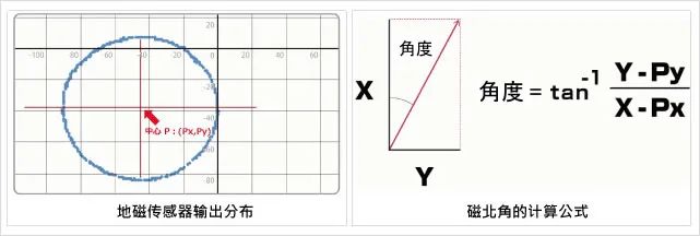
If the geomagnetic sensor rotates horizontally, under ideal conditions without the influence of surrounding magnetic fields, the center of the output distribution diagram becomes zero.
However, in reality, the center shifts due to the influence of the environmental magnetic field, so adjustments are needed to move the center to zero. The north pole derived from the geomagnetic sensor is called magnetic north (slightly offset from true north). By calculating the angle of this magnetic north using the above equation, the direction can be easily determined.
Types of Magnetic Sensors
Magnetic sensors are designed to measure the magnitude and direction of magnetic fields.
There are various sensors depending on the purpose, and typical sensors are listed below.
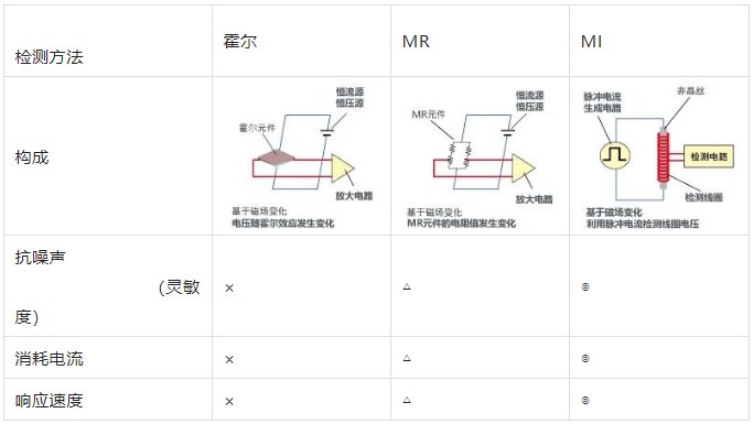
Hall Sensor
A sensor that measures magnetic flux density based on the Hall effect, outputting a voltage proportional to the magnetic flux density.
It is easy to use and mainly used in non-contact switch applications, such as detecting the opening and closing of doors and laptops.
MR Sensor
MR (Magneto Resistance) sensors, also known as magnetoresistive sensors, measure the magnitude of geomagnetism by utilizing changes in the resistance of an object due to a magnetic field.
With higher sensitivity than Hall sensors and lower power consumption, they are widely used magnetic sensors. In addition to geomagnetic detection applications like electronic compasses, they are also used in motor rotation and position detection applications.
MI Sensor
MI (Magneto Impedance) sensors are next-generation magnetic sensors that use special amorphous wire and apply the magneto-impedance effect.
Its sensitivity is more than 10,000 times higher than that of Hall sensors, and it can measure small changes in geomagnetism with high precision.
It can be applied in ultra-low current consumption orientation detection (electronic compass) and also in high-sensitivity applications such as indoor positioning and metal foreign object detection.
Pulse Sensor
A pulse wave is the waveform of the volume change of blood vessels when the heart sends blood, and the detector monitoring this volume change is called a pulse sensor.
First, there are four methods to measure heart rate: electrocardiogram, photoplethysmography, blood pressure measurement, and phonocardiography. Among these, photoplethysmography is the method using a pulse sensor for measurement.
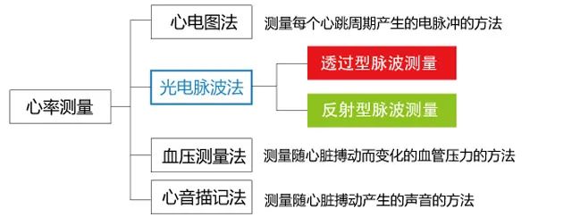
Due to differences in measurement methods, photoplethysmography pulse sensors can be of two types: transmission type and reflection type.
The transmission type measures the volume of blood flow that changes with the heartbeat by irradiating infrared or red light onto the body surface, measuring the change in light that passes through the body as the pulse wave.
This method is limited to measuring easily penetrable parts, such as fingertips and earlobes.
Reflection Type Pulse Sensor
The reflection type pulse sensor irradiates infrared light, red light, and green light of around 550nm wavelength onto the organism and uses a photodiode or phototransistor to measure the light reflected from the organism. Oxygenated hemoglobin present in arterial blood has the characteristic of absorbing incident light, so by detecting the changes in blood flow (changes in vascular volume) that vary over time with the heartbeat, the pulse signal is measured.
Additionally, since it measures reflected light, there is no need to restrict the measurement site as with the transmission type.
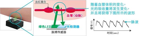
[Principle of Reflection Type Pulse Sensor]
When measuring pulse waves with infrared or red light, stable pulse wave measurements cannot be performed due to the influence of infrared light contained in outdoor sunlight. Therefore, it is recommended to use it only for indoor or semi-indoor applications.
For outdoor uses such as sports watches, the absorption rate of hemoglobin in blood is high, and since green light sources are less affected by ambient light, we use green LEDs as the irradiation light.
Applications of Pulse Sensors
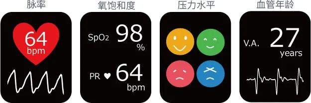
Typically, arterial blood oxygen saturation (SpO2) can be measured by observing the following two points. Observing the fluctuation period of the waveform obtained from the pulse sensor to monitor heart rate (pulse rate); using two wavelengths of infrared and red light to observe the pulsation (variability).
In addition, as an application of pulse sensors, it is expected to obtain various vital signs such as HRV analysis (stress level) and vascular age through high-speed sampling and high-precision measurement.
Barometric Sensor
The barometric sensor is a sensor that detects atmospheric pressure.
Depending on the pressure values to be measured, pressure sensors have various materials and methods as shown below. Among these pressure sensors, sensors that detect atmospheric pressure (for barometric detection) are commonly referred to as barometric sensors.
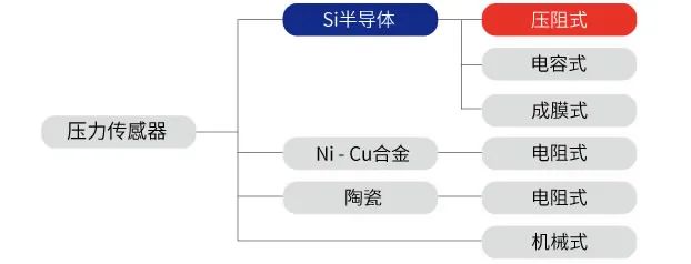
[Materials Used – Pressure Sensors Classified by Method]
A typical example of a barometric sensor is the piezoresistive type using silicon (Si).
The barometric sensor provided by ROHM is also a piezoresistive barometric sensor.Piezoresistive Barometric Sensor
The piezoresistive barometric sensor uses a Si single crystal plate as a diaphragm (pressure receiving element), forming a resistance bridge circuit by diffusing impurities on its surface, calculating pressure (barometric pressure) based on the change in resistance value caused by deformation when pressure is applied.
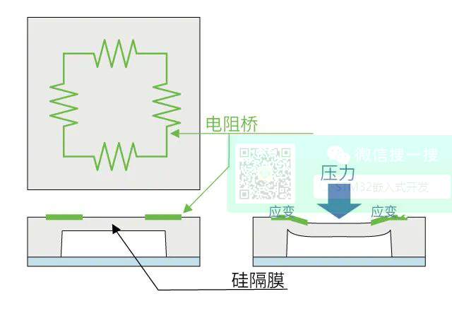
[Piezoresistive Barometric Sensor]
The phenomenon where resistivity (conductivity) changes due to pressure applied to the resistor is called the piezoresistive effect. ROHM’s barometric sensor IC integrates a piezoresistive pressure receiving element (diaphragm structure and piezoresistor combined※MEMS), along with temperature correction processing, control circuits, etc., all integrated into one package, allowing for easy acquisition of high-precision barometric information.
※ MEMS: Micro Electro Mechanical System
A device that integrates mechanical components, sensors, actuators (driving parts), etc., on a single circuit board.
※ ASIC: Application Specific Integrated Circuit
It is an integrated circuit that combines multiple circuit functions into one specific application.
Accelerometer
Acceleration refers to the speed generated per unit time, and the IC that measures acceleration is called an accelerometer.
By measuring acceleration, information about the tilt, vibration, and other characteristics of an object can be obtained.
The unit of acceleration is m/s² (※International System of Units SI).
Additionally, the unit G is the acceleration value based on standard gravity (1 G = 9.806 65 m/s²).
There is also a unit for detecting earthquake vibrations called Gal (CGS unit system).
※ International System of Units SI (French: Système international d’unités)
It is an international unit composed of length m, weight kg, time s (MKS unit).
※ Standard Gravity
The acceleration generated by an object under the influence of gravity. The increase in speed of an object per unit of time during free fall (9.806 65 m/s²).
※ Gal
The unit of acceleration in the CGS (length cm, weight g, time s) unit system. Defined as 1/100 of the SI unit (1 Gal = 0.01 m/s²).
Accelerometers are generally classified into low-G accelerometers and high-G accelerometers, as shown in the figure below.
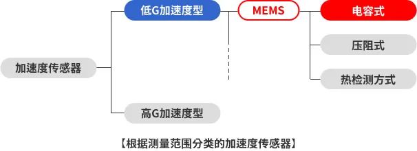
Capacitive Accelerometer
ROHM Group accelerometers are capacitive accelerometers using MEMS technology.
The sensor element consists of fixed electrodes, movable electrodes, and springs made of Si. In the state without applied acceleration, the distance between the fixed and movable electrodes is the same. When acceleration is applied, the movable electrode shifts. As a result, the relationship between the position of the electrodes changes, and the capacitance changes. The change in capacitance is converted into voltage through the※ASIC to calculate acceleration.
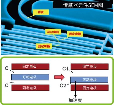
【Capacitive Principle】
※ ASIC
Application Specific Integrated Circuit
Refers to an integrated circuit that integrates multiple circuit functions for specific purposes.
Current Sensor
What is a Current Sensor?
A current sensor is a sensor that detects the current flowing in a circuit.Methods of Current Detection
As shown in the figure below, methods of detecting flowing current can be broadly divided into resistive detection type and magnetic field detection type.
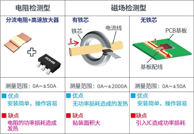
[Current Detection Methods and Characteristics]
The resistive detection type converts the voltage drop caused by a shunt resistor into current. It is easy to install and cost-effective, but the drawback is that power loss on the resistor generates significant heat. The magnetic field detection type
measures the magnitude of the magnetic field generated in the iron core based on the current flowing through the current line to measure the current value. This method does not require contact, has low power loss, but the iron core is large, posing a problem of larger mounting area.
Using the Hall effect, it converts the magnetic field generated around the flowing current into voltage (Hall voltage) to measure the current value. Since the voltage generated by the Hall effect is small, the IC consists of Hall elements and amplifying circuits. Since the current needs to be introduced into the IC, power loss occurs.M1 Current Sensor
To eliminate the disadvantages of the above magnetic field detection type (with iron core) in installation difficulty and (without iron core) in power loss, ROHM developed a non-contact current sensor using MI (Magneto Impedance) elements.
MI sensors, which use special amorphous wire and utilize their magneto-impedance effect, have the feature of ultra-high sensitivity in magnetic detection.
The sensitivity far exceeds that of Hall elements, allowing for high-precision detection of small changes in magnetism. Therefore, it can perform high-precision non-contact current detection (magnetic detection) without needing to introduce current into the package.
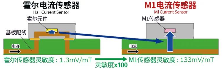
[Comparison of Current Sensor Structures (ROHM Survey)]
In summary, MI current sensors can perform non-contact current measurement, have low power loss, and can further reduce mounting area.
Color Sensor
Among light sensors (photo sensors), those that detect the three primary colors R (red), G (green), and B (blue) are called color sensors.
Color sensors receive surrounding light through photodiodes and detect RGB values.Principle of Color Sensors
Light with RGB components is irradiated onto an object, and the reflected light’s color components change according to the object’s color.
For example, the reflected light component of a red object is red; for a yellow object, it is red and green; and white includes all components of red, green, and blue.
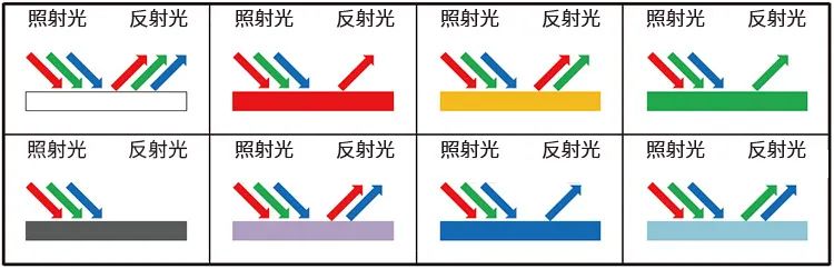
[Illustration of Object Reflected Light Color]
From this, it can be understood that the color of an object is determined by the ratio of the color light (R, G, B) components reflected by the object.
The human eye recognizes the color of an object by obtaining the reflected light components.
In complete darkness, nothing can be seen! This is because there is no incident light, and naturally, there is no reflected light, making it appear pitch black.
Similar to the human eye, the color sensor uses photodiodes to receive light and recognizes colors by calculating the ratio of the received R, G, and B amounts.Structure of Color Sensor IC
The diagram below shows the structure of the color sensor IC. It is equipped with color filters (Color filter) and infrared cut filters (Ir cut filter) inside.
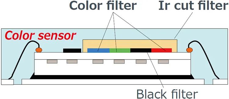
[Brief Structure of ROHM’s Representative Color Sensor]
The following compares the spectral characteristics of sensors with and without these filters.
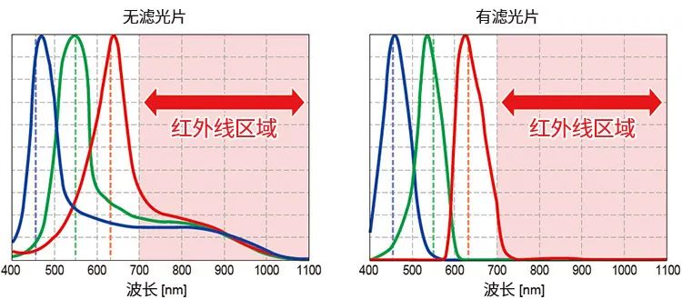
[RGB Spectral Characteristics Illustration]
The color sensor IC, by equipping the internal sensor with various color filters (R, G, B), has high RGB spectral characteristics, and by equipping an infrared cut filter, it has the characteristic of infrared removal, allowing for high-precision color recognition.