
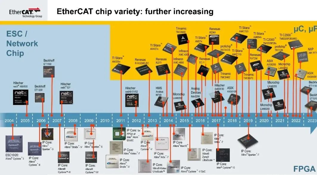
Image Source: EtherCAT Technology Group
Author: Robert B.Trask
“
The EtherCAT slave controller chips, along with diagnostic and development tools, help users enhance field communication performance and simplify debugging.
”
The EtherCAT Slave Controller (ESC) is a core concept of EtherCAT; it represents the chip-based part of EtherCAT field devices. The chips can be Application-Specific Integrated Circuits (ASICs), Field-Programmable Gate Arrays (FPGAs), microprocessors, or even microcontrollers. The ESC can handle the read and write of periodic and non-periodic data, as well as other background tasks required by flexible field buses.
Although EtherCAT network controllers do not require special hardware, using ESC chips at the field bus device level can benefit applications. Using ASICs in EtherCAT field devices allows processing to occur within the chip. Thus, the network performance is independent of the performance of the microcontroller in the device and its ability to run complex software stacks. Real-time protocol processing is embedded within the chip, and field devices do not have to manage typical Ethernet connections.
By implementing EtherCAT functionality in the ESC, EtherCAT systems can update 1000 distributed input/output (I/O) points every 30 microseconds. The “real-time data exchange” defined in the ESC only requires device configuration to utilize the protocol and inherent mechanisms built into the specific chip.
ESC Does Not Require an IP Stack
In a typical IP-based Ethernet, it is not uncommon for field buses to have field layer chip interfaces. This has historical roots in protocols such as CANopen, DeviceNet, and SERCOS. EtherCAT, for example, allows field devices to avoid providing sufficient processing power to handle IP-based Ethernet communication—saving not only processor costs, space, heat, and power but also reducing the complexity of using an IP stack.
EtherCAT uses the physical mechanisms of Ethernet without requiring a complete implementation of the seven-layer Open Systems Interconnection (OSI) model Ethernet stack in the field, simplifying development for device manufacturers and the application of EtherCAT. However, EtherCAT is not an IP-based protocol. EtherCAT is a field bus that uses standard IEEE 802.3 Ethernet without the need for complex configuration and powering of a complete Ethernet implementation.
Avoiding Complexity
Almost all ESCs provided by EtherCAT chip vendors are largely the same. Therefore, compared to other Ethernet-based technologies, device developers and system users will benefit from less programming. The functionality of EtherCAT field devices is built-in and only requires configuration. Since no software stack with unknown timing behavior is involved in the cycle period, system performance is predictable.
Because the ESC provides a universal interface, developers and users can leverage EtherCAT devices in a similar manner. Since the same diagnostic techniques are available for all EtherCAT devices, this also simplifies diagnostics. As there is only one version of EtherCAT, there will be no changes over time when using devices and network configurations in the field. The operation of the EtherCAT protocol and ESC also allows for the simple addition of new devices without worrying about adverse effects on the existing network.
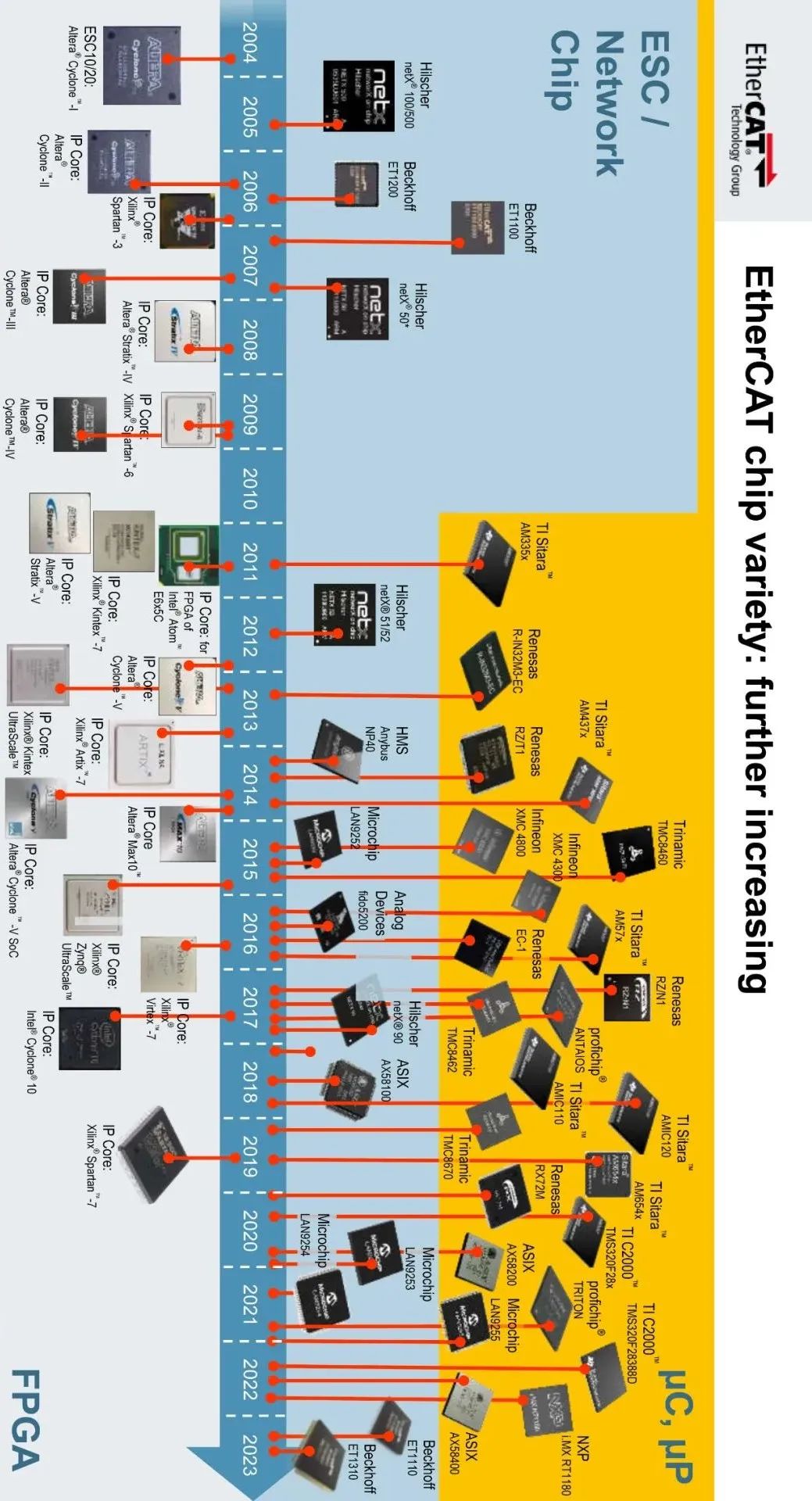
▎There are various options for EtherCAT slave controllers, with more options under development.
EtherCAT Slave Device Description File
EtherCAT devices have an .xml file, similar to the EDS files in CANopen, DeviceNet, and EtherNet/IP, as well as GSD files in Profibus and Profinet. This EtherCAT Slave Device Description (ESI) file contains the data required to configure and use the device. Each EtherCAT device comes with an ESI file that describes the device’s characteristics and functionalities. This means users can implement EtherCAT devices without needing to deeply understand the internal workings of the device or Ethernet.
Implementing EtherCAT field devices is very simple, without needing to deal with complex mechanisms. The focus is on controlling the machine or process, rather than configuring and tuning the network. The ESI file defines how the ESC operates using local I/O and higher-level processors. The configuration of field devices can be easily achieved through the ESI file and ESC.
Automatic Address Assignment
The ESC can also implement intelligent “automatic increment” instructions to automatically assign addresses to EtherCAT devices. With this feature, at startup, the controller identifies devices and their physical locations in the network, compares the actual network configuration with the expected configuration, and assigns addresses. All of this happens in the background, meaning there is no need to manually set the address for each node, nor to “set” each node one by one as in other networks. With EtherCAT, users do not need to deal with MAC or IP addresses, configure subnet masks, or any other settings related to ESC functionality.
Real-Time Processing and Reduced Jitter
EtherCAT uses standard, unmodified Ethernet frames in a unique and efficient way, overcoming the limitations of ordinary Ethernet technology. This method is applicable to all device implementations, including over 3000 EtherCAT device manufacturers. Through ESC and EtherCAT technology, there is no need to send and receive individual frames of Ethernet data, decode the data, and then copy process data to different devices. Instead, as the frame passes through the device, EtherCAT field devices read the data. The output data from field devices is also written as the frame passes through the ESC.
Since field devices find data through their position in the global process image, the frame does not need to carry device addresses. This means there is no “per node” overhead in the frame, and process data communication becomes very efficient. Additionally, the same frame, or even the same area within the frame, can be used simultaneously for input and output data, effectively doubling the bandwidth. ESC read/write data only takes a few nanoseconds.
Through ESC, EtherCAT uses standard Ethernet full-duplex technology and supports various topologies, including bus, tree, branch, and star models. Its physical layer includes 100BaseTX twisted pair, 100BASE-FX fiber optic, or Low-Voltage Differential Signaling (LVDS).

▎EtherCAT and ESC have a simple ISO/OSI stack.
Every 100 microseconds, 100 servo systems with 8-byte I/O data can be updated. At this rate, the system can read position and status and send new instructions and control data. Distributed clock technology is responsible for precise synchronization and reduces jitter (loop synchronization error for the drive) to below 1 microsecond.
Link Loss Detection
On the other hand, the ESC effectively uses inherent mechanisms of Ethernet. Ethernet communication is based on carrier signals (i.e., links), and the Frame Check Sequence (FCS) in frames is a cyclic redundancy check (CRC) that can detect transmission errors. EtherCAT and ESC utilize this in a very effective way with functionalities stronger than standard Ethernet chips. Each port of the ESC counts link losses and FCS errors. This allows users to determine and accurately locate events, even intermittent ones.
Intermittent errors have always been a challenge for any field bus. Because ESC can count every problem that occurs on each port, it helps identify issues. There is no need to guess or switch components blindly when necessary. So far, most issues have been physical problems, such as wiring, connectors, or components that may be stretched, pulled, and often mishandled.
Since all ESCs use the same mechanism, there is no need to worry about which vendor provides the field device. They all operate in the same way; no special software or troubleshooting tools are required. All they need to understand is how EtherCAT and ESC work to identify and resolve the root of the problem. The same tools and techniques can be used for all devices.
Implementation of Slave Stack Code
The Slave Stack Code (SSC) is implemented above the application layer on the ESC, without affecting network performance. The processing capability requirements for the ESC on the device processor are very low. The SSC has a royalty-free license and provides ASCII C processing: device status, cyclic (PDO) access, non-cyclic (SDO) access, and interrupts. This simplifies the development of EtherCAT devices. For these reasons, ESC and SSC provide a unique toolset in the field bus communication domain.
Key Concepts:
■ Understand how ESC becomes a chip-based solution for EtherCAT field devices.
■ Data exchange is defined within the ESC and requires device configuration to use the inherent mechanisms built into the protocol.
■ EtherCAT uses unmodified Ethernet frames, and ESC helps it operate efficiently.
Consider This:
Does less network programming benefit your Ethernet applications?
– END –

Inthefieldofcontrolengineeringandautomationindustryisincreasinglydependentonadvancedtechnologiesandinnovationstoimproveefficiencyandeffectivenessintheiroperationsandproductivity.Weinviteyouto