Sensors are tools for humans to perceive, acquire, and detect various information from nature, enabling the collection of vast amounts of information that human senses cannot obtain. In modern science and technology, industrial and agricultural production, and daily life, sensors play an irreplaceable role.It can be said that the more advanced the science and technology, the higher the degree of automation, the greater the reliance on sensors.
1. Composition of Sensors
Sensors typically consist of sensitive elements, conversion elements, and basic conversion circuits, as shown in Figure 1.
The sensitive element is a component that can sensitively perceive the measured scene and respond according to a defined relationship;
The conversion element converts the measured quantity sensed by the sensitive element into circuit parameters (such as resistance, inductance, and capacitance) or electrical quantities (such as voltage and current);
The basic conversion circuit converts the output of the conversion element into quantities that are easy to transmit and process.
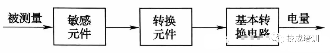
Figure 1 Composition of Sensors
Some sensors can consist only of sensitive elements and conversion elements, while others may combine the sensitive element and conversion element into one. The simplest sensor consists of a single sensitive element (which also serves as the conversion element) that can directly output electrical quantities when sensing the measured quantity, such as thermocouples, piezoelectric crystals, and photovoltaic cells.
2. Classification of Sensors
Sensors come in various types, and there are multiple classification methods. Here, we will only introduce two commonly used classification methods.
(1) Classification by Measured Physical Quantity. Sensors include displacement sensors, proximity sensors, speed sensors, temperature sensors, force sensors, torque sensors, pressure sensors, and acceleration sensors. This classification directly indicates the purpose of the sensor and corresponds to the various types of information concerned by users and sensor manufacturers, making it easier for users to understand and select sensors.
(2) Classification by Operating Principle. Sensors include resistive sensors, capacitive sensors, inductive sensors, piezoelectric sensors, Hall sensors, and photoelectric sensors. This classification method is based on the working principles of sensors, facilitating understanding and research of various sensors and their detection principles.
3. Basic Characteristics of Sensors
The characteristics of a sensor refer to the correspondence between the output quantity and the input quantity of the sensor. Since the input quantity can be static (i.e., the input signal does not change with time or changes very slowly in a fundamentally stable state) or dynamic (i.e., the input signal undergoes periodic changes or irregular transient changes over time), the characteristics of sensors usually have two corresponding representations: static characteristics and dynamic characteristics.
When the input quantity is static, the relationship between the sensor’s output and input quantity is referred to as the sensor’s static characteristics. Typically, the main indicators used to characterize the static characteristics of sensors include: measurement range, span, sensitivity, resolution, linearity, hysteresis, repeatability, drift, and stability.
1. Proximity Sensors
Proximity sensors can detect whether a measured object is approaching without contact and output the detection result as a switch signal; thus, they are often referred to as non-contact limit switches or proximity switches.
Proximity switches come in various types, including inductive, capacitive, photoelectric, and Hall effect types.
(1) Inductive Proximity Sensors. Inductive proximity sensors, also known as inductive proximity switches or eddy current proximity switches, are mainly composed of an LC high-frequency oscillation circuit, signal processing circuit, and switch amplification circuit, as shown in Figure 2.
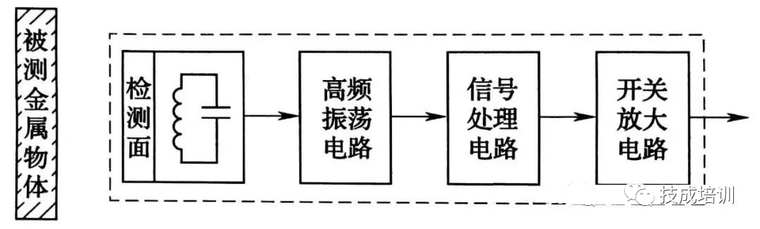
Figure 2 Schematic Diagram of Inductive Sensors
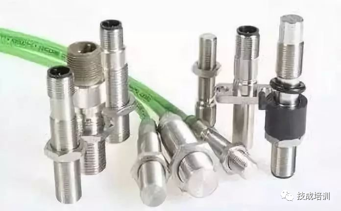
Figure 3 Physical Diagram of Inductive Proximity Sensors
(2) Capacitive Proximity Sensors. Capacitive proximity sensors, also known as capacitive proximity switches, have a circuit block diagram as shown in Figure 4.
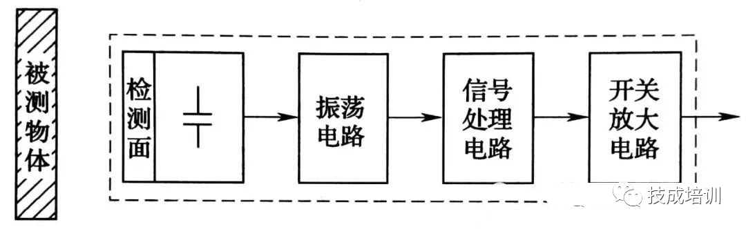
Figure 4 Schematic Diagram of Capacitive Sensors
Capacitive proximity switches use the plates of a capacitor as their sensing surface, and the material facing the sensing surface is the insulating medium between the two plates of the capacitor. If this insulating medium changes, the capacitance of the capacitor will also change.
Regardless of whether the measured object is metallic or non-metallic, when it approaches or moves away from the capacitive proximity switch, it will cause a change in the dielectric constant of the capacitor, enabling the capacitive proximity switch to output the corresponding switch signal.
Therefore, the objects detected by capacitive proximity switches are not limited to conductive metals but can also include insulating liquids or powdered materials. The capacitive proximity switch used is shown in Figure 5.
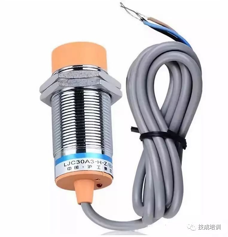
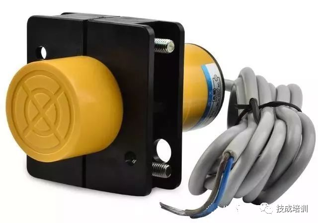
Figure 5 Physical Diagram of Capacitive Proximity Sensors
(3) Photoelectric Proximity Sensors. Photoelectric sensors are a type of sensor that uses photoelectric devices to convert light signals into electrical signals. The core sensitive element is the photoelectric device, which operates based on the photoelectric effect. Figure 6 shows a photoelectric proximity switch.
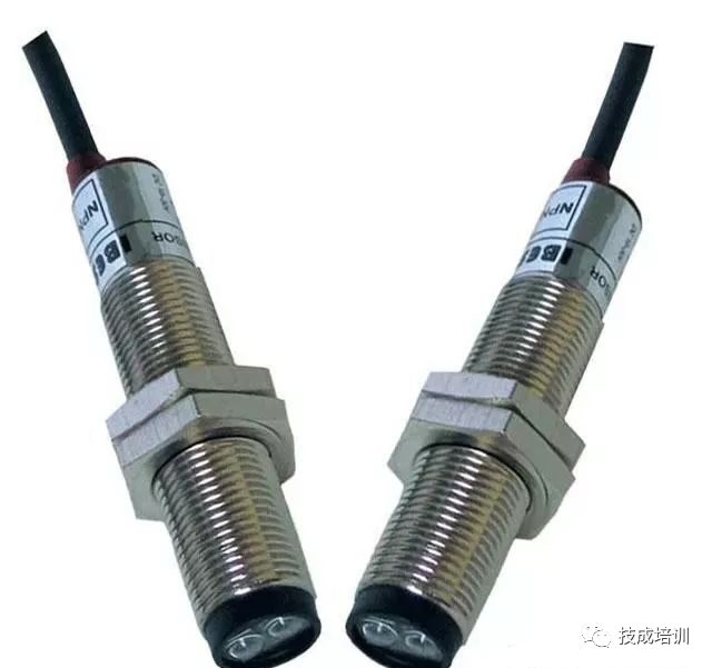
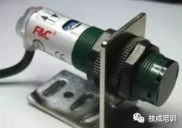
Figure 6 Physical Diagram of Photoelectric Proximity Sensors
2. Temperature Sensors
To meet the temperature measurement requirements for different occasions and materials, there are two methods for measuring temperature: contact and non-contact. The former involves direct physical contact between the sensing element and the object being measured, measuring temperature through thermal conduction; the latter involves measuring temperature through thermal radiation without physical contact between the sensing element and the object.
Each of the two temperature measurement methods has corresponding temperature sensors. Contact temperature sensors typically utilize the temperature characteristics of materials or components for measurement. Common temperature sensors include thermocouples, resistance temperature detectors, thermistors, and integrated temperature sensors. Figure 7 shows the Pt100 temperature sensor and temperature transmitter used in equipment.
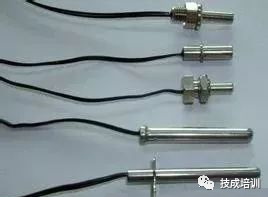
Figure 7 Physical Diagram of Temperature Sensors
3. Magnetic Switches
In automated production lines, magnetic switches are used for position detection of various cylinders, using two magnetic switches to measure the extended and retracted positions of the cylinder on the robotic arm.
Magnetic proximity switches (referred to as magnetic switches) are a type of non-contact position detection switch. This non-contact position detection does not wear out or damage the detection object, and has a high response speed.
Magnetic switches are used to detect the presence of magnetic materials, and there are various installation methods, including wired types, plug-in types, and plug-in relay types. Depending on the environmental requirements of the installation site, magnetic switches can be either shielded or unshielded. Their appearance is shown in Figure 8.
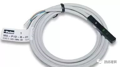
Figure 8 Physical Diagram of Magnetic Switches
4. Fiber Optic Photoelectric Proximity Switches
Fiber optic photoelectric proximity switches (referred to as fiber optic photoelectric switches) are also a type of fiber optic sensor. The sensing part of the fiber optic sensor has no circuit connections and does not generate heat, using very little light energy. These characteristics make fiber optic sensors an ideal choice for hazardous environments.
Fiber optic sensors can also be used for long-term high-reliability monitoring of critical production equipment. Compared to traditional sensors, fiber optic sensors have the following advantages: resistance to electromagnetic interference, ability to operate in harsh environments, long transmission distances, and long service life, in addition, due to the small size of the fiber optic head, they can be installed in very small spaces. The fiber optic amplifier can be set up as needed.
For example, in some production processes, smoke and sparks may cause explosions and fires, but light energy will not become an ignition source, thus preventing explosions and fires. The fiber optic detection head can be placed in hazardous locations, and the amplifier unit can be set up in non-hazardous locations for use.
Fiber optic sensors consist of a fiber optic detection head and a fiber optic amplifier. The fiber optic amplifier and the fiber optic detection head are two separate components. Fiber optic sensors are structurally divided into sensing types and light transmission types. Sensing types use the fiber optic itself as the sensitive element, allowing the fiber optic to perceive and transmit the measured information.
Light transmission types input light signals modulated by the measured object into the fiber optic, measuring through light signal processing at the output end. The working principle of light transmission type fiber optic sensors is similar to that of photoelectric sensors. In production, the light transmission type fiber optic photoelectric switch is used in the goods sorting unit, where the fiber optic serves merely as the transmission path for modulated light. Common fiber optic sensors are shown in Figures 9 and 10.
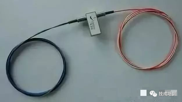
Figure 9 Physical Diagram of Fiber Optic Sensors
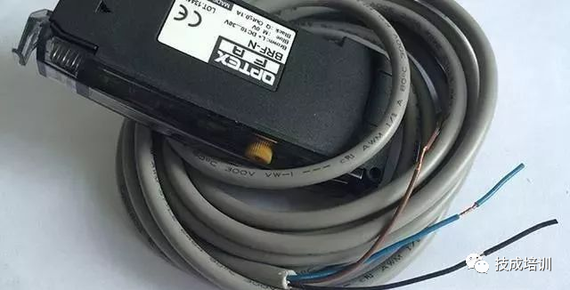
Figure 10 Physical Diagram of Fiber Optic Sensor Amplifiers
5. Photoelectric Encoders
Photoelectric encoders are sensors that convert mechanical and geometric displacement into pulses or digital quantities through photoelectric conversion, mainly used for detecting speed or position (angle).
A typical photoelectric encoder consists of a code disk, detection grating, photoelectric conversion circuit (including light source, photosensitive device, signal conversion circuit), mechanical components, etc.
Generally, based on the different ways in which photoelectric encoders generate pulses, they can be divided into incremental, absolute, and compound types. Incremental sensors are commonly used in production lines, and their structure is shown in Figure 11.
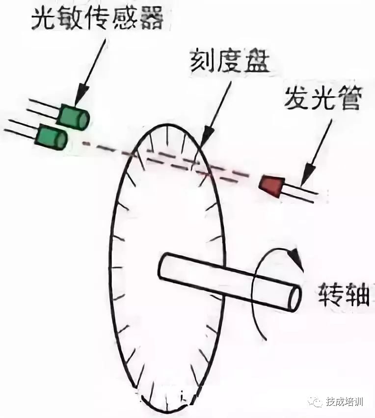
Figure 11 Schematic Diagram of Photoelectric Encoders
In general production equipment, the positioning control of conveyor belts is completed by photoelectric encoders. At the same time, photoelectric encoders also measure the speed of electric motors. Their appearance is shown in Figure 12.
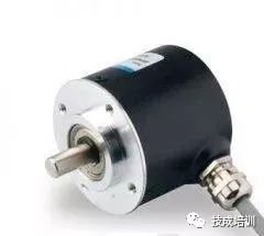
Figure 12 Physical Diagram of Photoelectric Encoders
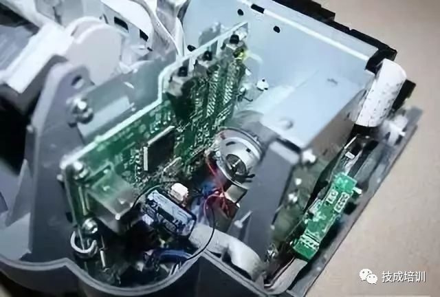
Figure 13 Usage of Photoelectric Encoders in Equipment
Disclaimer: This article is reproduced from the internet, and the copyright belongs to the original author. If there are any copyright issues, please contact us in time for removal. Thank you!
Complete Question Bank for 2022 Electrician Primary Exam (Includes Answers)
Three Must-Have Tools for Electricians, Easily Accessible via WeChat!
Collection: The “Path” of a Decade-Old Electrician, Secrets to Earning Over Ten Thousand a Month!
Which of the Five Major Electrical Drafting Software (CAD, Eplan, CADe_simu…) Do You Choose?
Latest Electrical Version CAD Drawing Software, with Detailed Installation Tutorial!
Latest Electrical Drawing Software EPLAN, with Detailed Installation Tutorial!
Common Issues for Beginners Using S7-200 SMART Programming Software (Includes Download Link)
Comprehensive Electrical Calculation EXCEL Spreadsheet, Automatically Generated! No Need for Electrical Calculation Help!
Bluetooth Headphones, Electrical/PLC Introductory Books Available for Free? Come and Claim Your Electrical Gifts!
Basic Skills for PLC Programming: Ladder Diagrams and Control Circuits (Includes 1164 Practical Cases of Mitsubishi PLC)
Still Can’t Understand Electrical Diagrams? Basic Electrical Diagram Recognition and Simulation Software Available for Quick Hands-On Learning!
12 Free Electrician Video Courses, 10GB Software/E-Book Materials, 30 Days of Free Electrician Live Classes Available!