
When printed circuit board assemblies (PCBA) return with corrosion, analysts need to find the source of contamination that caused the corrosion in order to eliminate it. Contaminants can come from various sources, such as manufacturing operations, packaging, installation, and the environment.
There are many methods that can be used to determine the composition of contaminants. Once the composition is known, potential sources can be identified. This article illustrates the process analysts use to identify the contamination sources of corroded PCBAs through an example.
A few corroded PCBAs were returned from a customer, and the PCBA had severe corrosion, but it only occurred in a few locations near one side. The corrosion images of two of the PCBAs are shown in Figure 1 and Figure 2.
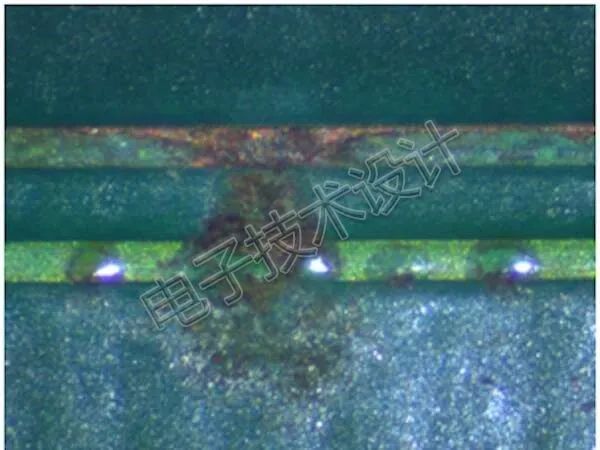
Figure 1: Open circuit on the PCBA.
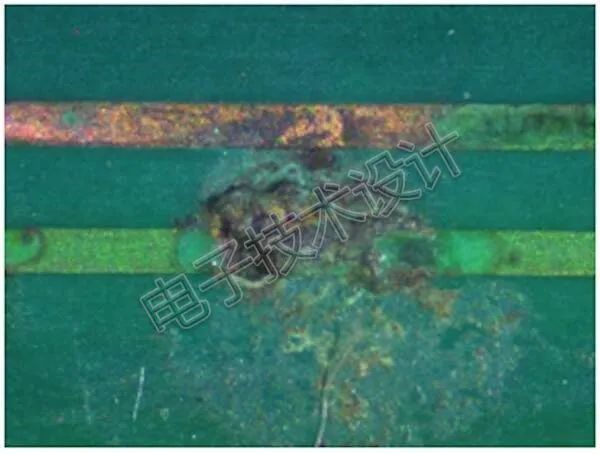
Figure 2: An open circuit can be seen in this image.
In both images, the lower conductors have open circuits. The solder mask has been removed from the conductors, exposing the copper which is severely oxidized. The charred epoxy between the conductors on both PCBAs indicates that a conductive phenomenon occurred between them. This suggests that the corrosion is essentially ionic corrosion and that there is a thin layer of water adhered to the PCBA due to environmental factors.
Element Identification
The corrosion areas were imaged using a scanning electron microscope (SEM). SEM is typically equipped with an energy-dispersive X-ray detector (EDX), which can determine the elemental composition of the sample. The EDX system cannot determine whether two elements are chemically bonded, but knowing which elements are present can provide insight into the chemical composition.
Figure 3 shows the SEM image of the contaminated area, from which EDX corrosion data can be obtained, as shown in Figure 4.
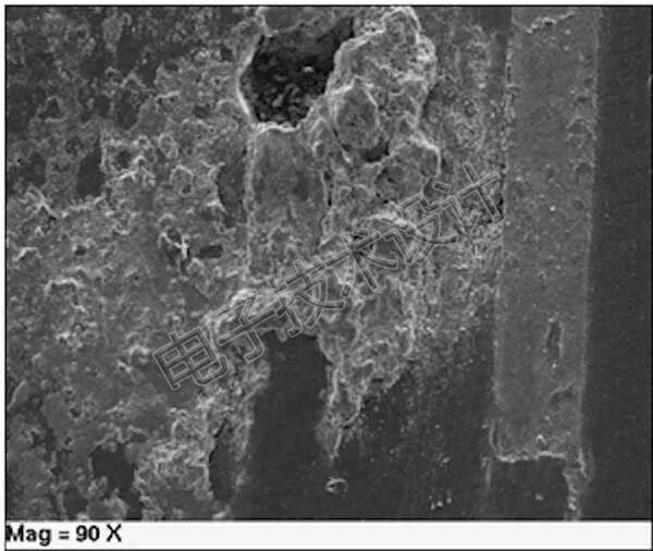
Figure 3: SEM image of the corrosion area. (Secondary electron imaging, SEI)
Figure 4 shows the typical EDX spectra of the solder mask layer near the corrosion area and the corrosion spectra. The blue spectrum comes from the non-corroded solder mask area, while the red spectrum is from the corroded area—these two spectra show significant differences.
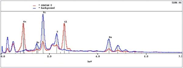
Figure 4: The y-axis of the spectrum indicates the detected X-ray counts, while the x-axis indicates the detected X-ray energy.
The solder mask (blue spectrum) contains silicon (Si), which is used to control the viscosity of the liquid solder mask before curing. It also contains barium (Ba) and sulfur (S), which combine to form barium sulfate used as a flame retardant. All these elements are expected to be present in the solder mask, as shown in the blue spectrum.
The contaminated area contains copper (Cu) and chlorine (Cl), which are not found in the solder mask. The copper comes from the copper conductors, which have been etched and chemically removed from the metal conductors, now deposited on the solder mask film. Chlorine is a contaminant that should not be present on the PCBA.
Chlorine can be found in many places in the environment—salt contains chlorine, and many chemicals used in the manufacturing of PCBAs also contain chlorine. However, these chemicals should not be the source of chlorine since they would be washed away during the washing process in PCBA manufacturing. Chlorine was not found in the solder mask samples, so the manufacturing process of the PCBA can be ruled out.
Chlorine has been used in the soldering process—to promote good solder connections, chlorinated compounds are added to the flux. These compounds can quickly remove any oxide layers on copper, resulting in good solder connections. However, during the transition from lead-free solder to RoHS-compliant solder, the type of flux used has also changed. Chlorinated rosin flux has been replaced with low-solids flux containing organic acids to clean the copper surface for soldering. During the soldering process, organic acids typically decompose into harmless products due to heating. These PCBAs were manufactured after the introduction of RoHS-compliant solder and used low-solids organic flux for manufacturing.
The corrosion is isolated to one area of the PCBA. If chlorine were present in the air due to salt mist or chlorine vapor, it would be present throughout the PCBA. Chlorine is used in various industrial processes (as well as in swimming pools), leading to the presence of chlorine and chlorinated compounds in the air of these areas.
A visual inspection of the PCBA revealed that several components near the corrosion area had undergone rework. The visual inspection indicated that the flux residue was not from the low-solids organic acid flux.
These reworked locations were examined using the SEM EDX system, which found chlorine in the flux residue. The presence of chlorine in the flux indicates that an old activated flux was used during the rework of the components. The source of this flux was then found in the assembly workshop and eliminated as a corrective action—there was a workstation for rework that had a bottle of old liquid flux that had not been removed from the factory.
If chlorine had not been traced back to the flux used during the rework process, this necessary corrective action might not have been taken, and corrective actions might have been implemented in several potential locations to eliminate contamination. In this specific case, the activated rosin flux was a remnant of the previous process that had not been cleared from this rework station. Other measures to eliminate contamination would be ineffective. Corrective actions must be based on the evidence collected during the investigation. If a shotgun approach were used to eliminate chlorinated flux, the bottle of flux might not be found at any single rework station, leaving the problem unresolved.
How EDX Works?
Within the sample, when electrons change their energy and fill vacancies in atoms, the EDX system captures the X-rays generated. It counts the number of X-rays captured at each energy level. Each electron around the atomic nucleus has a specific energy, which varies by element. Because these energies differ, the atomic composition of the sample can be determined.
The electrons emitted by the SEM interact with the electrons of each atom. In some cases, this interaction causes an atom’s electrons to escape, leaving a vacancy. If the atom has a second electron with a higher energy filling this vacancy, a certain amount of energy must be released. The released energy appears in the form of X-rays of specific energy or wavelength. By capturing and measuring these X-rays, a list of the elements present can be compiled. The software of the EDX system then displays the data in a chart—the energy of the X-rays is shown on the horizontal axis, while the number of counted X-rays is shown on the vertical axis.

Click to read the original article, free gift
Market Price
192