1. Main Body
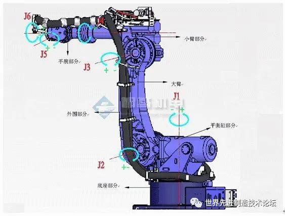
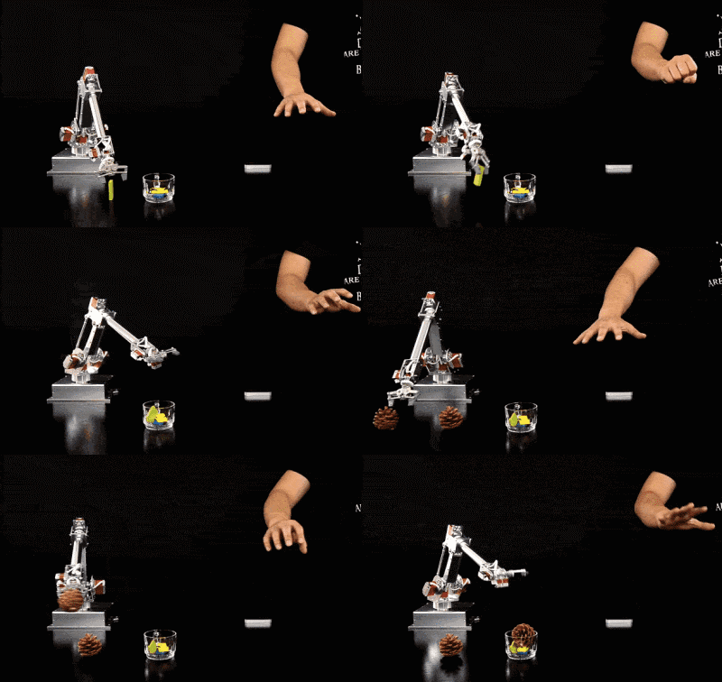
The main mechanical body consists of the base and the actuating mechanism, including the upper arm, lower arm, wrist, and hand, forming a multi-degree-of-freedom mechanical system. Some robots also have walking mechanisms. Industrial robots typically have six degrees of freedom or even more, with the wrist usually having 1 to 3 degrees of active freedom.
2. Drive System
The drive system of industrial robots is categorized into three main types based on the power source: hydraulic, pneumatic, and electric. Depending on requirements, these three types can also be combined into composite drive systems. Alternatively, they can be indirectly driven through mechanical transmission mechanisms such as synchronous belts, gear trains, and gears. The drive system includes power devices and transmission mechanisms to execute corresponding actions of the actuating mechanism, and each of these three basic drive systems has its own characteristics, with electric drive systems being the mainstream today.
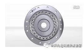
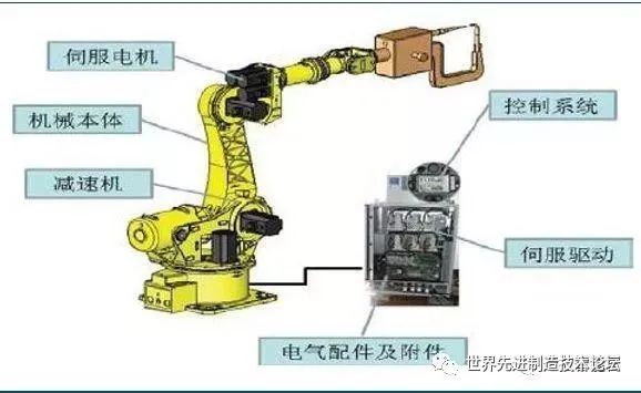
Due to low inertia, high torque AC and DC servo motors and their associated servo drivers (inverter, DC pulse width modulator) are widely adopted. This type of system does not require energy conversion, is easy to use, and has sensitive control. Most motors require precise transmission mechanisms such as gear reducers to be installed behind them. Their gears use gear speed converters to reduce the motor’s rotation speed to the desired speed while achieving higher torque, thereby reducing speed and increasing torque. When the load is large, merely increasing the power of the servo motor is not cost-effective; instead, increasing output torque through gear reducers within an appropriate speed range is more feasible. Servo motors tend to overheat and exhibit low-frequency vibrations during low-frequency operations, and prolonged repetitive work is detrimental to ensuring their accuracy and reliable operation. The existence of precision gear reducers allows servo motors to operate at suitable speeds while enhancing the rigidity of the machine body and outputting greater torque. Currently, the mainstream gear reducers are of two types: harmonic reducers and RV reducers.
3. Control System
The robot control system is the brain of the robot and is the main factor determining its functionality and performance. The control system issues command signals to the drive system and actuating mechanism based on the input program and conducts control. The main task of industrial robot control technology is to control the robot’s range of motion, posture, trajectory, and timing of actions within its workspace. It features easy programming, software menu operation, a user-friendly human-computer interaction interface, online operation prompts, and ease of use.
The controller system is the core of the robot, and foreign companies have been closely monitoring experiments in China. In recent years, with the development of microelectronics technology, the performance of microprocessors has improved while their prices have dropped significantly; currently, 32-bit microprocessors are available on the market for 1-2 USD. The high cost-performance ratio of microprocessors has brought new development opportunities for robot controllers, making it possible to develop low-cost, high-performance robot controllers. To ensure that the system has sufficient computing and storage capacity, most robot controllers now use strong chips from ARM series, DSP series, POWERPC series, Intel series, etc.
As existing general-purpose chips cannot fully meet the requirements of some robot systems in terms of price, performance, integration, and interfaces, the demand for SoC (System on Chip) technology has emerged in robot systems, integrating specific processors with required interfaces to simplify the design of peripheral circuits, reduce system size, and lower costs. For example, Actel integrates the NEOS or ARM7 processor cores into its FPGA products, forming a complete SoC system. In terms of robot technology controllers, research is mainly concentrated in the United States and Japan, with mature products such as those from DELTATAU in the USA and PONTEK in Japan. Their motion controllers are based on DSP technology and adopt an open structure based on PC.
4. Perception System
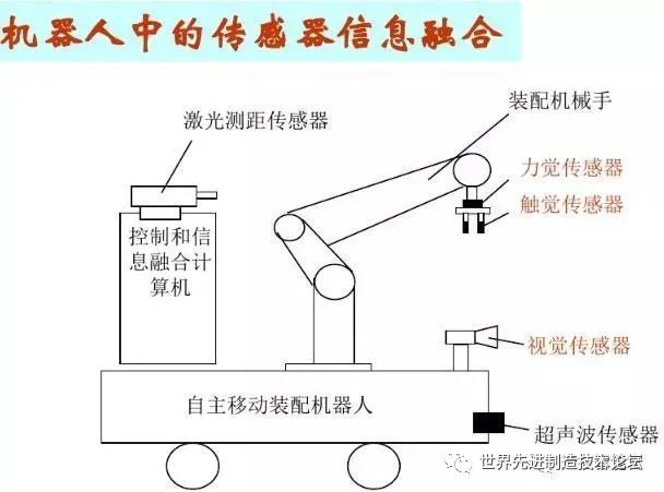
It consists of internal sensor modules and external sensor modules that obtain meaningful information about the internal and external environmental states.
Internal sensors: These sensors detect the robot’s own status (such as the angles between arms) and are mostly used to detect position and angle. Specific types include position sensors, angle sensors, etc.
External sensors: These sensors detect the environment in which the robot is located (such as detecting objects and the distance to objects) and their conditions (such as detecting whether the objects being grasped are slipping). Specific types include distance sensors, vision sensors, force sensors, etc.
The use of intelligent sensing systems has improved the mobility, practicality, and intelligence standards of robots. While the human sensory system is agile in perceiving external world information, sensors can be more effective than human systems for certain specific information.
5. End Effector
The end effector is the component connected to the last joint of the robotic arm, typically used for grasping objects, connecting with other mechanisms, and executing required tasks. Robot manufacturers generally do not design or sell end effectors; in most cases, they only provide a simple gripper. Typically, end effectors are mounted on the flange of the robot’s six axes to complete tasks in a given environment, such as welding, painting, gluing, and loading/unloading parts, which are tasks that require robots to accomplish.
Overview of Servo Motors
Servo drivers, also known as “servo controllers” or “servo amplifiers,” are controllers used to control servo motors, functioning similarly to how inverters operate on standard AC motors, and are part of the servo system. Generally, they control servo motors through three methods: position, speed, and torque, achieving high-precision transmission system positioning.
1. Classification of Servo Motors
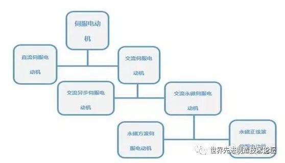
They are divided into two main categories: DC and AC servo motors. AC servo motors are further divided into asynchronous servo motors and synchronous servo motors, with AC systems gradually replacing DC systems. Compared to DC systems, AC servo motors have advantages such as high reliability, good heat dissipation, low inertia, and the ability to operate under high voltage conditions. Because they are brushless and do not use commutators, AC servo systems are also referred to as brushless servo systems, and the motors used are brushless structured squirrel cage asynchronous motors and permanent magnet synchronous motors.
1) DC servo motors are divided into brushed and brushless motors
① Brushed motors are low-cost, simple in structure, have high starting torque, a wide speed range, easy control, but require maintenance (replacing carbon brushes), generate electromagnetic interference, and have environmental requirements. They are typically used in cost-sensitive ordinary industrial and civilian applications;
② Brushless motors are compact, lightweight, produce high output, respond quickly, operate at high speeds, have low inertia, provide stable torque, and offer smooth rotation. They have complex control, are intelligent, and have flexible electronic commutation methods, capable of square wave or sine wave commutation. They require no maintenance, are highly efficient and energy-saving, produce low electromagnetic radiation, have low temperature rise, and a long lifespan, making them suitable for various environments.
2. Characteristics of Different Types of Servo Motors
1) Advantages and disadvantages of DC servo motors
Advantages: Precise speed control, stiff torque-speed characteristics, simple control principles, ease of use, and low cost.
Disadvantages: Brush commutation, speed limitations, additional resistance, and generation of wear particles (not suitable for dust-free or explosive environments).
2) Advantages and disadvantages of AC servo motors
Advantages: Good speed control characteristics, smooth control can be achieved throughout the speed range, almost no oscillation, over 90% high efficiency, low heat generation, high-speed control, and high precision position control (depending on encoder accuracy). In the rated operating area, constant torque can be achieved, with low inertia, low noise, and no brush wear, requiring no maintenance (suitable for dust-free, explosive environments).
Disadvantages: Control is more complex, driver parameters need to be adjusted on-site to determine PID parameters, requiring more wiring.
Currently, mainstream servo drivers use digital signal processors (DSP) as the control core, enabling the implementation of relatively complex control algorithms, achieving digitization, networking, and intelligence. Power devices generally use driver circuits designed around intelligent power modules (IPM), which integrate driving circuits internally and feature fault detection protection circuits for overvoltage, overcurrent, overheating, and undervoltage. Soft start circuits are also added to the main circuit to reduce the impact on the driver during the startup process.
The power drive unit first rectifies the input three-phase power or mains through a three-phase full-bridge rectifier circuit to obtain the corresponding DC power. The rectified three-phase power or mains is then driven by a three-phase sine PWM voltage inverter to drive three-phase permanent magnet synchronous AC servo motors. The entire process of the power drive unit can be simply described as an AC-DC-AC process. The rectification unit (AC-DC) mainly consists of a three-phase full-bridge uncontrolled rectifier circuit.
3. Servo System Wiring Diagram
1. Driver Wiring
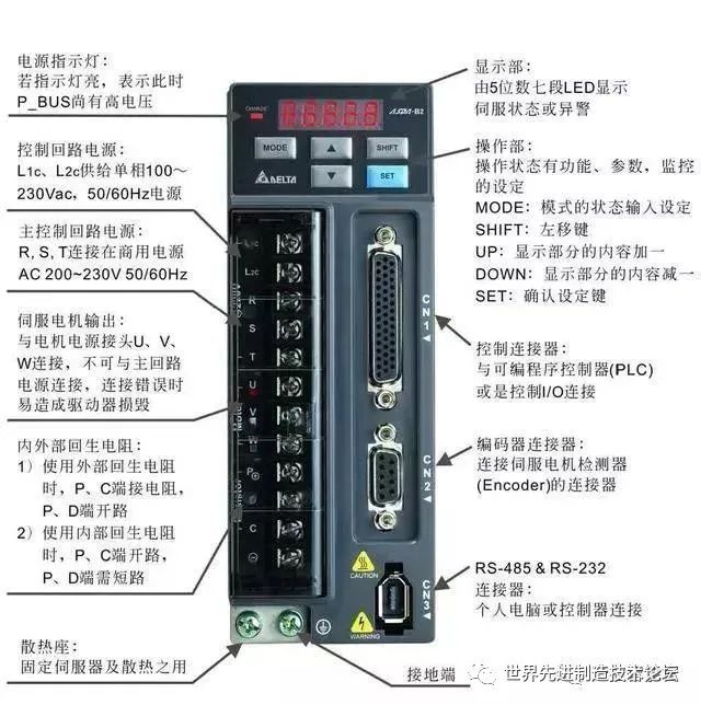
The servo driver mainly has control loop power supply, main control loop power supply, servo output power supply, controller input CN1, encoder interface CN2, and connection port CN3. The control loop power supply is a single-phase AC power supply, and the input power can be single-phase or three-phase, but it must be 220V. This means that when using three-phase input, our three-phase power supply must be transformed before connecting. For relatively small power drivers, single-phase direct driving is possible, and the single-phase connection must be to the R and S terminals. The servo motor outputs U, V, and W must not be connected to the main circuit power supply, as this may burn out the driver. The CN1 port is mainly used for connecting to the upper computer controller, providing input, output, encoder ABZ three-phase output, and various monitoring signal analog outputs.
2. Encoder Wiring
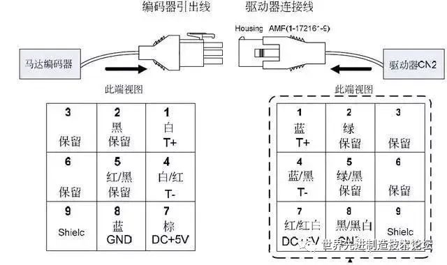
From the diagram above, we can see that out of the nine terminals, we only use five: one shielded wire, two power wires, and two serial communication signals (+ and -), which are similar to our ordinary encoder wiring.
3. Communication Port
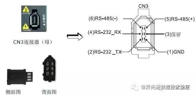
The driver connects to the upper computer such as PLC, HMI, etc. via the CN3 port, using MODBUS communication to control the driver, and can communicate using RS232 or RS485.
4. Servo Driver Market
Robots have very strict requirements for joint drive motors, and AC servo motors are widely used in industrial robots. Currently, the high-end domestic market is mainly occupied by foreign well-known companies, mainly from Japan and Europe and America, with a large space for domestic replacement in the future. Currently, foreign brands occupy nearly 80% of the Chinese AC servo market, mainly from Japan and Europe and America. Among them, Japanese products hold the largest market share of about 50%, with well-known brands including Panasonic, Mitsubishi Electric, Yaskawa, Sanyo, Fuji, etc. Their products are characterized by technology and performance levels that meet the needs of Chinese users, achieving stable and continuous customer sources with good cost-effectiveness and high reliability, especially having a monopoly advantage in the small and medium-sized OEM market.
Precision Reducers
Recently, I saw a piece of news: the robot industry needs to overcome the “bottleneck” problem, which resonated with me. With the increase in labor costs, industrial robots replacing humans have become a trend. As the cornerstone of intelligent manufacturing, industrial robots are constrained by core components, and according to relevant surveys, domestic robot reducers are generally reliant on imports. For the robot industry in China to flourish, it must resolutely solve the problem of core components.
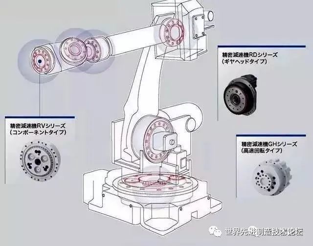
Next, we introduce the core precision components of industrial robots: reducers. Compared to general reducers, robot reducers require characteristics such as short transmission chains, small size, high power, light weight, and ease of control. In the reducer industry, we must mention the two giants: Nabtesco (also known as Nabtesco) and Hamonica Drive (Hamonica), colloquially known as RV reducers and harmonic reducers. They almost monopolize the global market for robot reducers. Both types of reducers are processed with micrometer-level precision, which is quite challenging even during mass production stages in terms of reliability, let alone at high speeds of thousands of revolutions, while also needing high longevity. Currently, the reducers widely applied in industrial robots are mainly of two types: RV reducers and harmonic reducers.
RV Reducers: They use low-tooth difference engagement, but compared to harmonic reducers, RV reducers typically use cycloidal pin wheels, consisting of cycloidal pin wheels and planetary carriers. The key to RV reducers lies in the processing and assembly processes. RV reducers have higher fatigue strength, rigidity, and longevity, unlike harmonic transmissions, which significantly reduce motion accuracy over time. Their disadvantage is that they are heavier and larger in size. RV reducers are used in the joints of industrial robots with high torque, such as the legs, waist, and elbows, with loads on the first, second, and third axes typically using RV reducers.
They possess much higher fatigue strength, rigidity, and longevity compared to the commonly used harmonic drives in robots and maintain stable backlash accuracy, unlike harmonic drives, which significantly reduce motion accuracy with prolonged use. Therefore, many countries in the world use RV reducers for high-precision robot drives, indicating a trend of gradually replacing harmonic reducers with RV reducers in advanced robot drives.
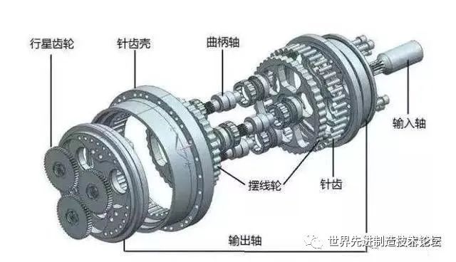
RV Reducer Disassembly Diagram
Harmonic Reducers: They also use low-tooth difference engagement, and a key gear in harmonic drives is flexible, requiring repeated high-speed deformation, making it relatively fragile with limited load-bearing capacity and longevity.
Harmonic reducers are a type of harmonic drive device, which includes harmonic accelerators and harmonic reducers. Harmonic reducers mainly consist of: rigid wheels, flexible wheels, and a radial deformable wave generator. They utilize flexible gears to create controllable elastic deformation waves, causing relative tooth misalignment between the rigid and flexible wheels to transmit power and motion. This type of transmission fundamentally differs from conventional gear transmissions in terms of engagement theory, aggregate calculations, and structural design. Harmonic gear reducers have advantages such as high precision and high load-bearing capacity. Compared to ordinary reducers, they use 50% less material, reducing their size and weight by at least one-third. Therefore, harmonic reducers are mainly used in small robots, characterized by their small size, light weight, high load capacity, and high motion accuracy, with large single-stage transmission ratios. They are generally used for smaller loads in industrial robots or for several axes at the end of large robots.
Harmonic Reducer Disassembly Diagram
Japan’s Nabtesco company proposed the RV-type design in the early 1980s and achieved substantial breakthroughs in RV reducer research by 1986, taking 6-7 years; whereas domestic companies such as Nantong Zhikang and Hengfengtai also spent 6-8 years to achieve results. Does this mean that local enterprises in China have no opportunities? Fortunately, after years of layout, Chinese enterprises have finally made some breakthroughs. Major domestic suppliers include Nantong Zhikang, Qinchuan Machine Tool, Wuhan Jinghua, Zhejiang Hengfengtai, and Zhejiang Shuanghuan Drive. It is said that Nantong Zhikang’s output has already exceeded 10,000 units, and Qinchuan Machine Tool’s production line has been opened, with output gradually increasing. The Qinchuan Machine Tool project is a national import substitution project, with a total investment of 314 million yuan for the production line of 90,000 sets of industrial robot joint reducers.
Control System
The robot control system is the brain of the robot and is the main factor determining its functionality and performance. The control system issues command signals to the drive system and actuating mechanism based on the input program and conducts control. The following article mainly introduces the robot control system.
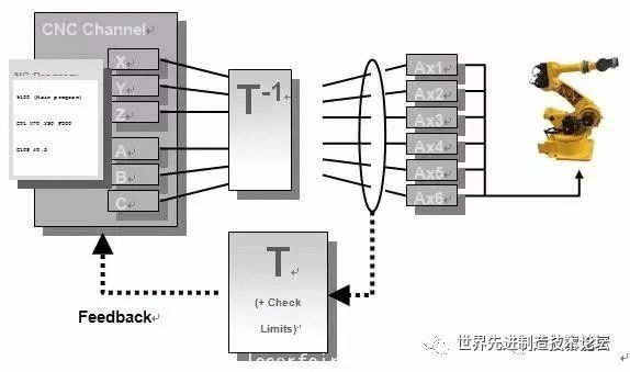
1. Robot Control System
The purpose of “control” is to ensure that the controlled object behaves as expected by the controller. The basic condition for “control” is to understand the characteristics of the controlled object.
The “essence” is the control of the output torque of the driver. The robot’s control system
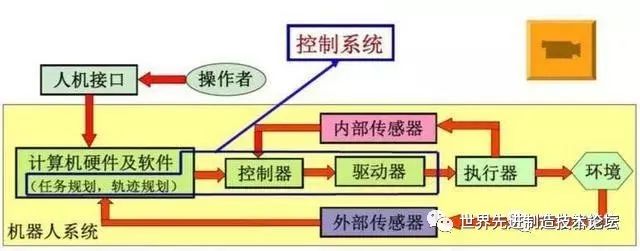
2. Basic Working Principle of Robots
The working principle is teaching and reproduction; teaching, also known as guided teaching, involves manually guiding the robot through the required action flow step by step, during which the robot automatically memorizes each action’s posture, position, process parameters, motion parameters, etc., and automatically generates a continuous execution program. After teaching, the robot only needs a start command to automatically complete the entire process according to the taught actions;
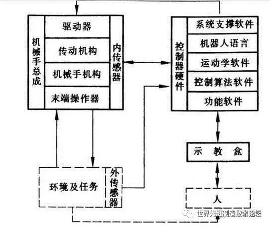
3. Classification of Robot Control
1) Divided into open-loop control and closed-loop control based on feedback.
Open-loop precise control conditions: precisely knowing the model of the controlled object and ensuring that this model remains unchanged during the control process.
2) Divided into force control, position control, and hybrid control based on desired control quantities.
Position control is divided into: single joint position control (position feedback, position speed feedback, position speed acceleration feedback), multi-joint position control.
Multi-joint position control is divided into decomposed motion control and centralized control, while force control is divided into: direct force control, impedance control, and force-position hybrid control.
3) Intelligent control methods include fuzzy control, adaptive control, optimal control, neural network control, fuzzy neural network control, and expert control.
4. Hardware Configuration and Structure of Control Systems: Electrical Hardware, Software Architecture
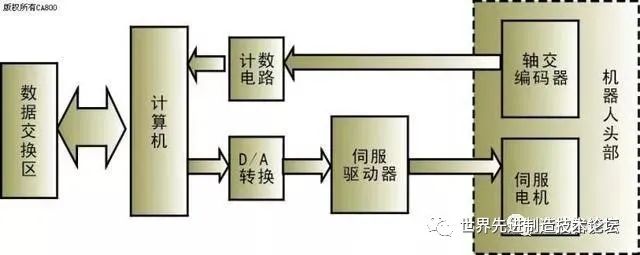
Due to the large number of coordinate transformations and interpolation calculations involved in the robot’s control process, as well as lower-level real-time control, most robot control systems on the market currently adopt a layered structure of microcomputer control systems, typically using two-level computer servo control systems.
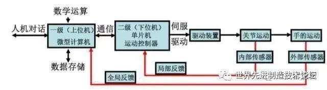
1) Specific process:
The master control computer receives the job instructions input by the staff, first analyzes and interprets the instructions, and determines the motion parameters of the hand. It then performs kinematic, dynamic, and interpolation calculations, ultimately deriving the coordinated motion parameters for each joint of the robot. These parameters are output to the servo control level via communication lines as set signals for each joint’s servo control system. The servo drivers on the joints convert this signal from D/A and drive each joint to produce coordinated motion.
Sensors feed back the motion output signals of each joint to the servo control level computer, forming a local closed-loop control to achieve precise control of the robot’s motion in space.
2) Motion Control Based on PLC: Two Control Methods:
① Using the output port of the PLC to produce pulse instructions to drive the motor while using general I/O or counting components to achieve closed-loop position control of the servo motor.
② Using an external position control module of the PLC to achieve closed-loop position control of the motor. This method mainly involves generating high-speed pulses for control, belonging to position control methods, which are generally more common in point-to-point position control.
Important Parameters of Robots
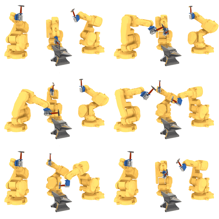
This article focuses on the technical parameters of industrial robots, with detailed graphical descriptions, hoping to help everyone!!
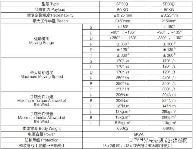
The technical parameters of robots reflect their capabilities and highest operational performance, which are essential considerations in robot design and application. The main technical parameters of robots include degrees of freedom, resolution, workspace, working speed, and working load.
1. Degrees of Freedom
It refers to the number of independent axes of motion that the robot possesses.
The degrees of freedom of a robot refer to the number of independent motion parameters required to determine the position and posture of the robot’s hand in space. The number of degrees of freedom of a robot generally equals the number of joints.
Common robots typically have 5 to 6 degrees of freedom. Some robots also have external axes.
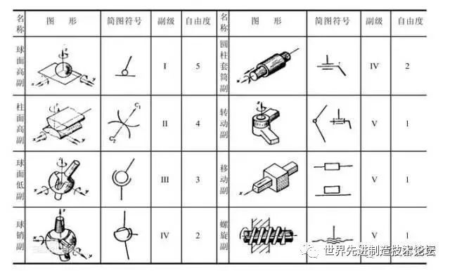
2. Joints
Also known as motion pairs, they are mechanisms that allow relative motion between the various components of the robotic arm.
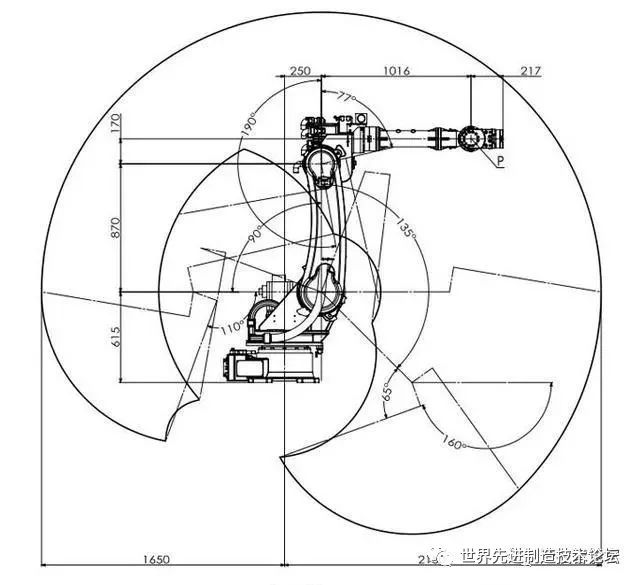
3. Working Range
The entire spatial range that the robotic arm or hand installation point can reach.
The shape of this range depends on the number of degrees of freedom of the robot and the types and configurations of its motion joints. The working range of robots can generally be represented by two methods: graphical and analytical.
4. Speed
It refers to the distance moved or angle rotated by the center of the mechanical interface or tool center point per unit of time during uniform motion under load conditions.
5. Working Load
This refers to the maximum weight that the robot’s wrist can bear at any position within its working range, generally expressed in terms of mass, torque, and moment of inertia.
It is also related to the parameters of running speed and acceleration, with the working load generally indicated by the weight of the workpiece that the robot can grasp during high-speed operation.
The load weight for handling robots must take into account the combined weight of the gripper and workpiece.

6. Resolution
It refers to the minimum movement distance or minimum rotation angle that the robot can achieve.
7. Accuracy
Repeatability or repeat positioning accuracy: It refers to the variability in reaching a target position repeatedly. For example, if you require an axis to move 100 mm, but the first time it actually moves 100.01 mm and the second time it moves 99.99 mm, the difference of 0.02 mm is the repeat positioning accuracy. It measures the concentration of a series of error values, i.e., repeatability. The accuracy of the robot is not only dependent on the joint reducer and transmission device but also has a significant relationship with the mechanical assembly process, as many issues arise from improper assembly, leading to decreased repeat positioning accuracy.
Disclaimer: This article is a network reprint, and the copyright belongs to the original author. However, due to numerous reprints, it is impossible to confirm the true original author, so only the source is indicated. If the videos, images, or texts used in this article involve copyright issues, please inform us immediately, and we will confirm the copyright based on the proof materials you provide and pay remuneration according to national standards or delete the content immediately!The content of this article reflects the original author’s views and does not represent the views of this public account or its authenticity.
Reprinted from: “Industrial Robots”