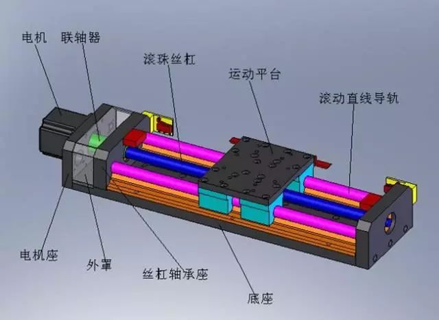
1. Use PLC to control a one-dimensional motion platform to achieve automatic forward and reverse operation of the motor as well as manual forward and reverse operation;
2. There are limit switches at both ends of the one-dimensional motion platform, defined as the forward limit and reverse limit respectively;
3. Before the motor can automatically run forward and backward, it needs to be reset. The reset process is as follows: start the motor to run in reverse until it reaches the reverse limit, then run forward a certain distance, which will be set as the initial position for automatic forward and reverse operation;
4. After reset is complete, press the forward button to run the motor forward for a certain distance (this distance is set through the motion envelope parameters), and stop when in position. Press the reverse button to run the motor backward for a certain distance, and stop when in position;
5. If during the forward and reverse operation, the limit switch is triggered, the motor will stop running. At this point, the motor can be controlled to move away from the limit switch using the manual forward and reverse buttons, or the reset button can be pressed to reset the platform;
6. After triggering the limit switch, reset is required before automatic forward and reverse operation control can be resumed;
7. During the motor operation, at any time, the “stop button” and “emergency stop button” can be used to control the motor to stop running;
8. After stopping, it is necessary to reset before automatic forward and reverse operation control can be resumed;
9. The “reset indicator”, “running indicator”, and “stop indicator” are used to indicate the running status of the one-dimensional platform.
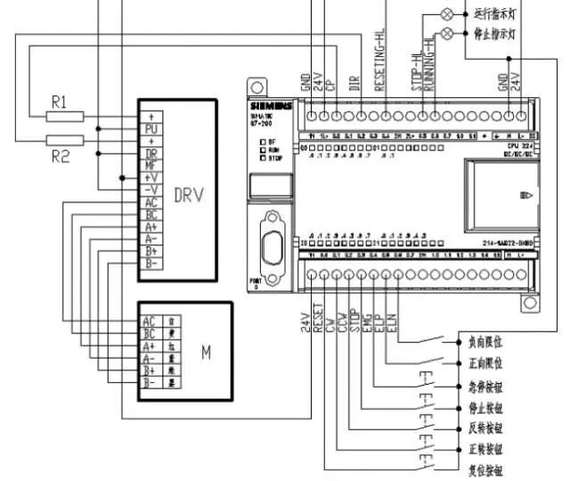
The S7-200 CPU provides two high-speed pulse output points (Q0.0 and Q0.1), which can work in PTO (Pulse Train Output) and PWM (Pulse Width Modulation) modes respectively. Using PTO or PWM can achieve open-loop motion control of speed and position.
The PTO function can output a series of pulses, and the user can control the period (frequency) and the number of pulses. The PWM function can continuously output a series of pulses with adjustable duty cycle, allowing the user to control the period and pulse width (duty cycle).
High-speed pulse output points share the output image Q0.0 and Q0.1 with ordinary digital output points. When the PTO or PWM function is activated on Q0.0 and Q0.1, the PTO/PWM generator has control over the output, and the output waveform is unaffected by others.
Only transistor output type CPUs can support high-speed pulse output functions.
An envelope (Profile) is a pre-defined curve with position as the horizontal coordinate and speed as the vertical coordinate, representing the graphical description of motion.
An envelope consists of multiple segments, each containing an acceleration and deceleration process to reach the target speed, followed by a series of specified pulses running at the target speed. If it is a single-segment motion control or the last segment of multi-segment motion control, it should also include a deceleration process from the target speed to stop.
PTO mainly achieves position control through the envelope. Position control can be realized by creating an envelope through parameter settings, displaying the envelope curve graphically, and automatically generating subprograms for position control.
Before starting to write the program, set the motion envelope first, the steps are as follows:
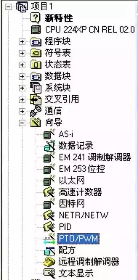
(1) Double-click the “Wizard—PTO/PWM” shown in the left image to open the “Pulse Output Wizard” window.
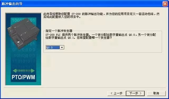
(2) Select Q0.0, and click “Next”.
(3) Choose “Linear Pulse Train Output (PTO)” and click “Next”.
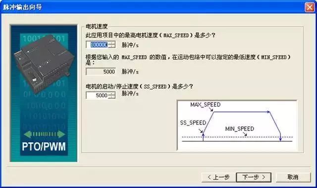
(4) Set the maximum speed, minimum speed, and motor start/stop speed for the application.
(5) Click “Next” to set the acceleration and deceleration time.
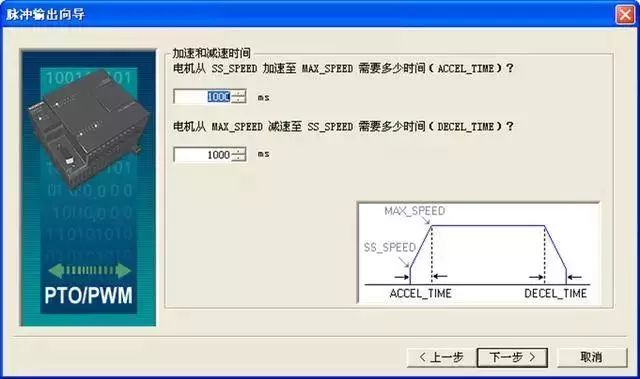
(6) Click “Next”.
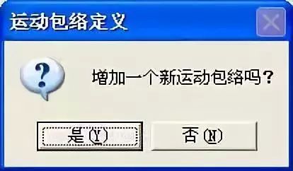
(7) Click “New Envelope” and select “Yes”.
(8) In the gray part of Figure 27, select “Relative Position” and set the parameters. Make sure that the target position of step 0 is not set too small, it needs to be greater than the sum of acceleration and deceleration pulse counts.
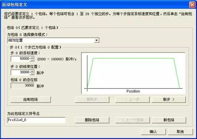
(9) Click “Confirm”.
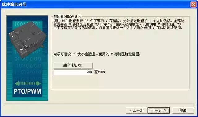
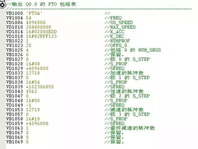
(10) Change the parameter “VB0” to “VB1000”, and be careful not to redefine “VB1000—VB1069” in the program; click “Next”.
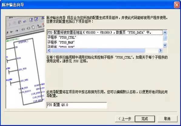
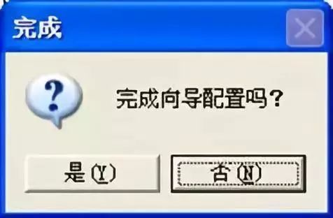
(11) Click “Finish”, and select “Yes” in the pop-up dialog.
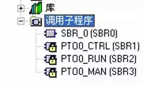
(12) The motion envelope setting is complete. In the calling subprogram, the position control subprogram corresponding to Q0.0 appears.
1. Power-on Initialization
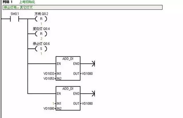
SM0.1: This bit is opened during the first scan cycle and is used to call the initialization subprogram.
2. Motor Control Subprogram and Initialization
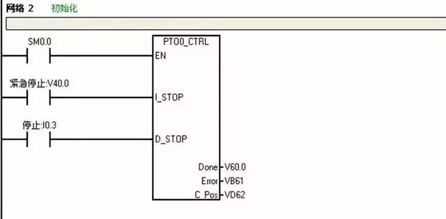
PTO0_CTRL is only used once in the program and is executed during each scan, so SM0.0 is used as the EN input.
EN: Enable terminal, connected to SM0.0, kept normally on;
I_STOP: When valid, the motor stops immediately;
D_STOP: When valid, the motor decelerates to stop;
Done: Completion flag. When “1”, indicates the previous instruction has completed;
Error: Displays error code, “0” indicates no error;
C_Pos: When the HSC counter function is enabled, it indicates the number of running pulses, otherwise it is 0.
3. Reset
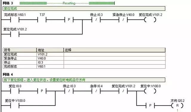
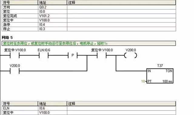
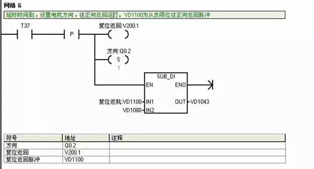
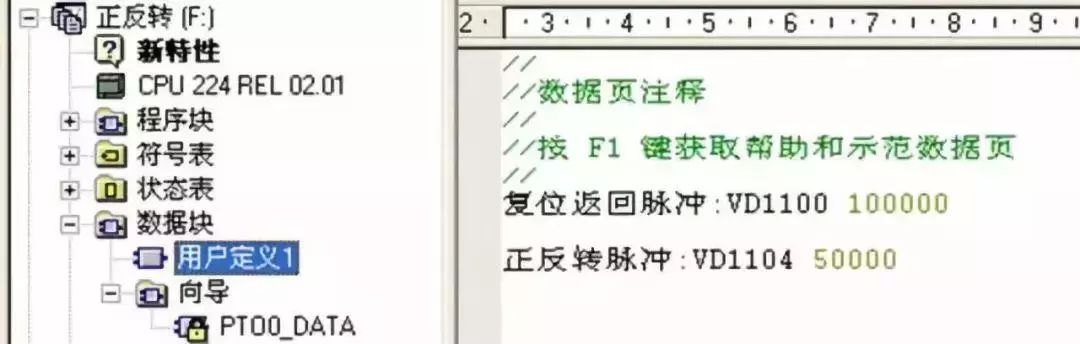
VD1100: Reset return pulse count, set in the data block “User Defined 1”. Based on the motor’s reduction ratio and the driver’s subdivision as well as the motor stroke settings.
VD1043: Running envelope constant speed segment pulse count; VD1100 – VD1080 = VD1043.
4. Forward Operation
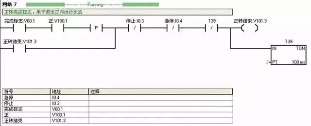
VD60.1: Motion envelope completion flag, “Done” parameter in PTO0_CTRL; v100.1: Forward operation status; v101.3: Forward operation end;
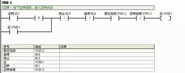
I0.1: Forward button;
V100.1: Forward operation status; V101.2: Reset completion flag. Reset must be completed before automatic forward and reverse operation;
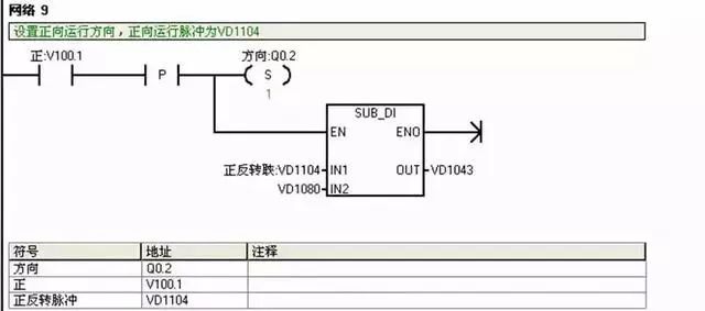
Q0.2: Motor direction;
VD1104: Forward and reverse pulse count, same as VD1100 parameter, set in “User Defined 1” in the “Data Block”. VD1104 – VD1080 = VD1043.
5. Reverse Operation
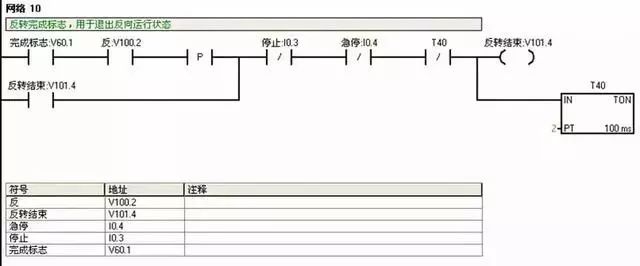
VD60.1: Motion envelope completion flag, “Done” parameter in PTO0_CTRL; v100.2: Reverse operation status; v101.4: Reverse operation end;
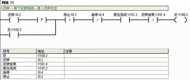
I0.2: Reverse button; V100.2: Reverse operation status; V101.2: Reset completion flag. Reset must be completed before automatic forward and reverse operation;
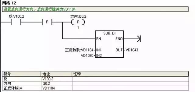
Q0.2: Motor direction;
VD1104: Forward and reverse pulse count, same as VD1100 parameter, set in “User Defined 1” in the “Data Block”. VD1104 – VD1080 = VD1043.
6. Manual Forward
Manual forward is a point control of the motor, requiring the button to be pressed continuously for the motor to run. When it reaches the forward limit, it cannot run even if the button is pressed, and can only run in reverse.
7. Manual Reverse
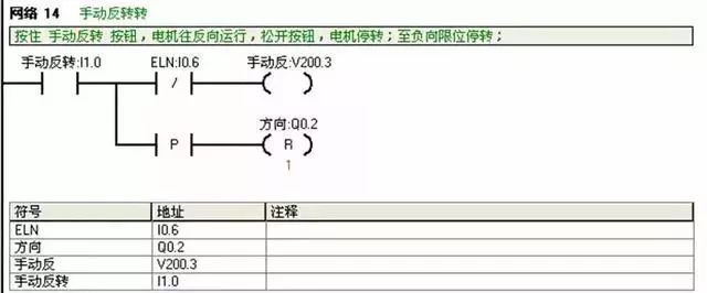
Manual reverse is a point control of the motor, requiring the button to be pressed continuously for the motor to run. When it reaches the reverse limit, it cannot run even if the button is pressed, and can only run forward.
8. Emergency Stop
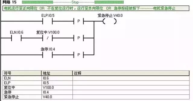
Emergency stop: A protective strategy for the system when reaching the forward and reverse limits. Under any circumstances, pressing the emergency stop button will cause the system to stop immediately.
9. Output
(1) Envelope Operation
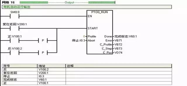
EN: Enable terminal, connected to SM0.0 indicating kept normally on;
START: When this parameter is enabled, the motion envelope is executed. To ensure the command is sent only once, use the rising edge signal;
Profile: The set motion envelope number;
Abort: Position control module stop parameter. When enabled, stop running the current envelope and decelerate to stop;
Done: Completion flag. This parameter is “1” when the module completes this subprogram;
Error: Error code, “0” indicates no error;
C_Profile: Contains the currently executing profile of the position control module;
C_Step: The currently executing profile step;
C_Pos: If the HSC counter function of the PTO wizard is enabled, the C_Pos parameter contains the module represented by the number of pulses; otherwise, this value is always 0.
(2) Jog Operation
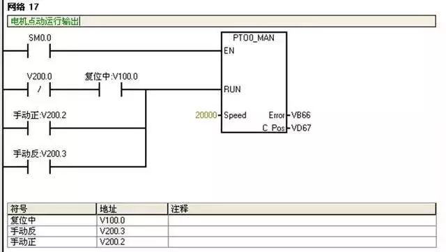
EN: Enable terminal, SM0.0 kept normally on;
RUN: Enable this parameter to accelerate to the set speed, disable this parameter to decelerate the motor to stop;
Speed: Set the maximum speed for manual operation;
Error: This subprogram’s error code, “0” indicates no error;
C_Pos: If the HSC counter function of the PTO wizard is enabled, the C_Pos parameter contains the module represented by the number of pulses; otherwise, this value is always zero.
(3) Indicator Lights
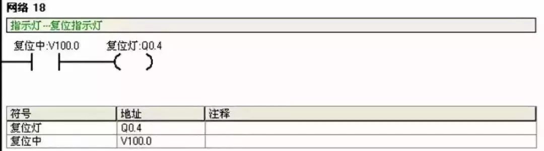
When in reset state, the reset indicator light is on.
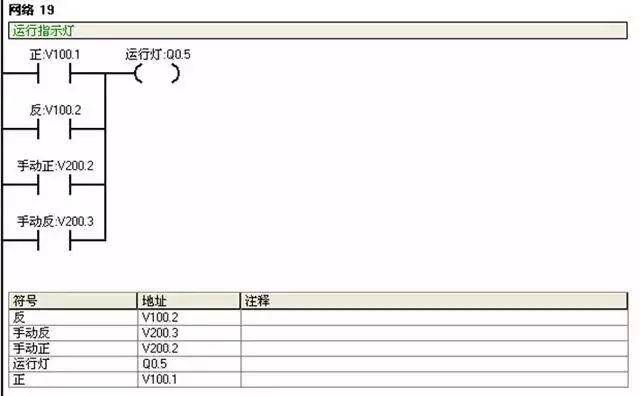
When running forward and backward, the running indicator light is on.
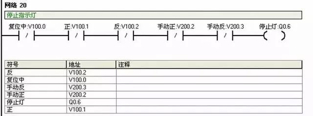
When not in reset or running state, the stop light is on.
Disclaimer: This article is reprinted from the internet, and the copyright belongs to the original author. If there are any copyright issues, please contact us in time for deletion, thank you!

Receive the most completeMitsubishi, Siemens PLC Instruction List
Also includedBasic materials for PLC beginners, programming examples