
Click the aboveblue text to follow us
In embedded systems, the Serial Peripheral Interface (SPI) and its extensions (such as DSPI and QSPI) are widely used for high-speed communication with external devices (such as sensors, memory, LCD controllers, etc.).
The main differences are as follows:
1
SPI
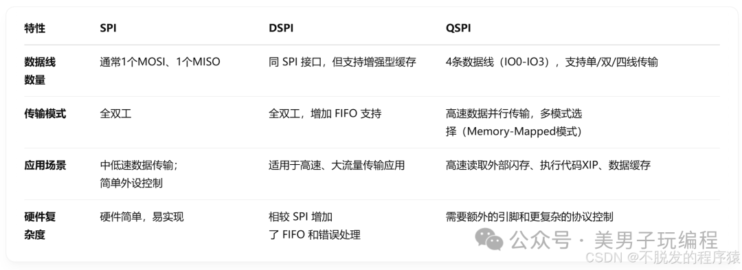
SPI (Serial Peripheral Interface) is a full-duplex synchronous serial communication protocol, typically consisting of a master device and one or more slave devices. The SPI bus mainly has the following four signal lines:
- SCLK (Serial Clock): Generated by the master device to provide the clock signal;
- MOSI (Master Out Slave In): Data sent from the master device to the slave device;
- MISO (Master In Slave Out): Data sent from the slave device to the master device;
- CS/NSS (Chip Select/Slave Select): Used by the master device to select the target slave device for communication.
The advantages of SPI include a simple structure, fast transmission rates, and flexible implementation. However, its disadvantages include limited bandwidth on a single data line during high-speed communication and complex hardware connections and line management when multiple slave devices are present.
The following C language pseudocode demonstrates the SPI initialization configuration and data transmission process based on a common MCU:
// SPI initialization functionvoid SPI_Init(void) { // Configure pin modes: SCLK, MOSI, MISO, CS ConfigGPIO(SCLK_PIN, GPIO_MODE_AF_PP); ConfigGPIO(MOSI_PIN, GPIO_MODE_AF_PP); ConfigGPIO(MISO_PIN, GPIO_MODE_AF_PP); ConfigGPIO(CS_PIN, GPIO_MODE_OUTPUT_PP); // Configure SPI peripheral parameters: master mode, data bits, polarity, phase, baud rate, etc. SPI_HandleTypeDef hspi; hspi.Instance = SPI1; hspi.Init.Mode = SPI_MODE_MASTER; hspi.Init.Direction = SPI_DIRECTION_2LINES; hspi.Init.DataSize = SPI_DATASIZE_8BIT; hspi.Init.CLKPolarity = SPI_POLARITY_LOW; hspi.Init.CLKPhase = SPI_PHASE_1EDGE; hspi.Init.NSS = SPI_NSS_SOFT; hspi.Init.BaudRatePrescaler = SPI_BAUDRATEPRESCALER_16; hspi.Init.FirstBit = SPI_FIRSTBIT_MSB; SPI_Init(&hspi); SPI_Enable(&hspi);}// SPI data transmission and receptionuint8_t SPI_TransmitReceive(uint8_t txData) { uint8_t rxData = 0; SPI_Transmit(&hspi, &txData, 1); SPI_Receive(&hspi, &rxData, 1); return rxData;}2
DSPI
DSPI (also known as Dual Serial Peripheral Interface on some platforms) is an interface that evolved from traditional SPI by adding more hardware features.
Taking the Freescale/NXP DSPI module as an example, its main features include:
- Enhanced data buffering capability: Internal multi-level FIFO buffer design reduces the risk of data loss due to software response delays;
- More flexible frame format configuration: Supports more bit-width configurations, continuous data transfer modes, and multi-master mode support;
- High-speed transmission capability: Optimized clock management and error detection mechanisms for high bandwidth requirements.
This makes DSPI a mainstream interface that has replaced traditional SPI in many modern MCUs.
From the user interface perspective, DSPI maintains a similar signal structure (SCLK, MOSI, MISO, CS) to standard SPI, but has made the following enhancements in hardware and data transmission efficiency:
- FIFO buffer support: Reduces the burden of interrupt service routines on high-speed data transmission;
- More flexible bus configuration: Some DSPI modules can support dual-channel parallel transmission, further increasing throughput;
- Error detection and recovery mechanisms: Provide more reliable communication guarantees.
These improvements make DSPI perform better in scenarios involving multitasking, high-speed, and large data volume transmission.
The following pseudocode demonstrates the DSPI initialization process, which is similar to SPI but includes configurations for enhanced features like FIFO:
// DSPI initialization function (based on specific MCU library, example for reference only)void DSPI_Init(void) { // Configure IO pins (similar to SPI) ConfigGPIO(SCLK_PIN, GPIO_MODE_AF_PP); ConfigGPIO(MOSI_PIN, GPIO_MODE_AF_PP); ConfigGPIO(MISO_PIN, GPIO_MODE_AF_PP); ConfigGPIO(CS_PIN, GPIO_MODE_OUTPUT_PP); // Configure DSPI controller parameters DSPI_HandleTypeDef hdspi; hdspi.Instance = DSPI1; hdspi.Init.Master = ENABLE; hdspi.Init.Direction = DSPI_DIRECTION_2LINES; hdspi.Init.DataSize = DSPI_DATASIZE_8BIT; hdspi.Init.CLKPolarity = DSPI_POLARITY_LOW; hdspi.Init.CLKPhase = DSPI_PHASE_1EDGE; hdspi.Init.NSS = DSPI_NSS_SOFT; hdspi.Init.BaudRatePrescaler = DSPI_BAUDRATEPRESCALER_8; // Configure built-in FIFO buffer depth hdspi.Init.FIFOThreshold = DSPI_FIFO_THRESHOLD_4; DSPI_Init(&hdspi); DSPI_Enable(&hdspi);}3
QSPI
QSPI (Quad SPI) is designed to meet the demands for high-speed data transmission, especially suitable for external Flash memory. Compared to traditional SPI, QSPI not only has standard SCLK and CS but also adds four bidirectional data pins (IO0, IO1, IO2, IO3), supporting multiple data transfer modes (single/dual/quad line modes), with the following characteristics:
- Expanded data lines: QSPI increases the theoretical transmission rate by 4 times through parallel data transmission;
- Memory-mapped mode: Supports direct mapping of external FLASH to MCU memory space, enabling zero-copy reads;
- Flexible transmission protocol: Common command sequences include address phase, dummy commands, and data transfer phase, suitable for large-capacity memory applications.
Typical QSPI transmission operations can be divided into the following phases:
- Command sending phase: The host sends read/write commands to the external device;
- Address transmission phase: Sends the memory address (usually 24 bits or 32 bits);
- Data transmission phase: Multiple data lines transmit data simultaneously, significantly reducing transmission latency compared to SPI;
- Status query/end: Determines whether to continue subsequent operations based on device response.
This protocol supports memory-mapped mode, allowing external devices to be used as memory, making it very suitable for code execution (XIP, eXecute In Place) and high-speed data caching scenarios.
The following code demonstrates the QSPI module initialization and basic data reading operation in pseudocode (specific APIs may vary significantly depending on the vendor’s SDK):
// QSPI initialization functionvoid QSPI_Init(void) { // Configure QSPI pins: SCLK, CS, IO0-IO3 ConfigGPIO(QSPI_SCLK_PIN, GPIO_MODE_AF_PP); ConfigGPIO(QSPI_CS_PIN, GPIO_MODE_AF_PP); ConfigGPIO(QSPI_IO0_PIN, GPIO_MODE_AF_PP); ConfigGPIO(QSPI_IO1_PIN, GPIO_MODE_AF_PP); ConfigGPIO(QSPI_IO2_PIN, GPIO_MODE_AF_PP); ConfigGPIO(QSPI_IO3_PIN, GPIO_MODE_AF_PP); // Configure QSPI controller parameters QSPI_HandleTypeDef hqspi; hqspi.Instance = QSPI1; hqspi.Init.ClockPrescaler = 2; hqspi.Init.FlashSize = 23; // Assuming capacity is 8 Mbit (2^23) hqspi.Init.SampleShifting = QSPI_SAMPLE_SHIFTING_HALFCYCLE; hqspi.Init.FlashID = QSPI_FLASH_ID_1; hqspi.Init.DualFlash = QSPI_DUALFLASH_DISABLE; QSPI_Init(&hqspi); QSPI_Enable(&hqspi);}// QSPI data reading example (simplified process)void QSPI_Read(uint32_t address, uint8_t* buffer, uint32_t size) { QSPI_CommandTypeDef cmd; cmd.Instruction = 0x03; // Normal read command cmd.Address = address; cmd.AddressSize = QSPI_ADDRESS_24_BITS; cmd.DummyCycles = 8; cmd.DataMode = QSPI_DATA_4_LINES; // Use quad line mode to read data QSPI_Receive(&hqspi, &cmd, buffer, size);}4
Selection Recommendations
Low-speed/simple applications: When the application does not have high transmission rate requirements, using SPI can meet the communication needs of most peripherals, and the interface is simple and compatible.
High-speed/high data volume applications: When the system has high demands for data throughput and real-time performance, adopting DSPI can fully utilize its FIFO buffering and high-speed transmission advantages.
Large capacity storage and XIP: For applications requiring memory mapping and high data bandwidth, such as reading external NOR Flash memory and executing external code, QSPI is the best choice.
In actual projects, system resources, peripheral interface requirements, and performance bottlenecks will all affect the final choice. It is recommended to conduct thorough evaluations and tests during the early design phase to ensure the selection of the most suitable solution.

 Click to read the original article for more exciting content~