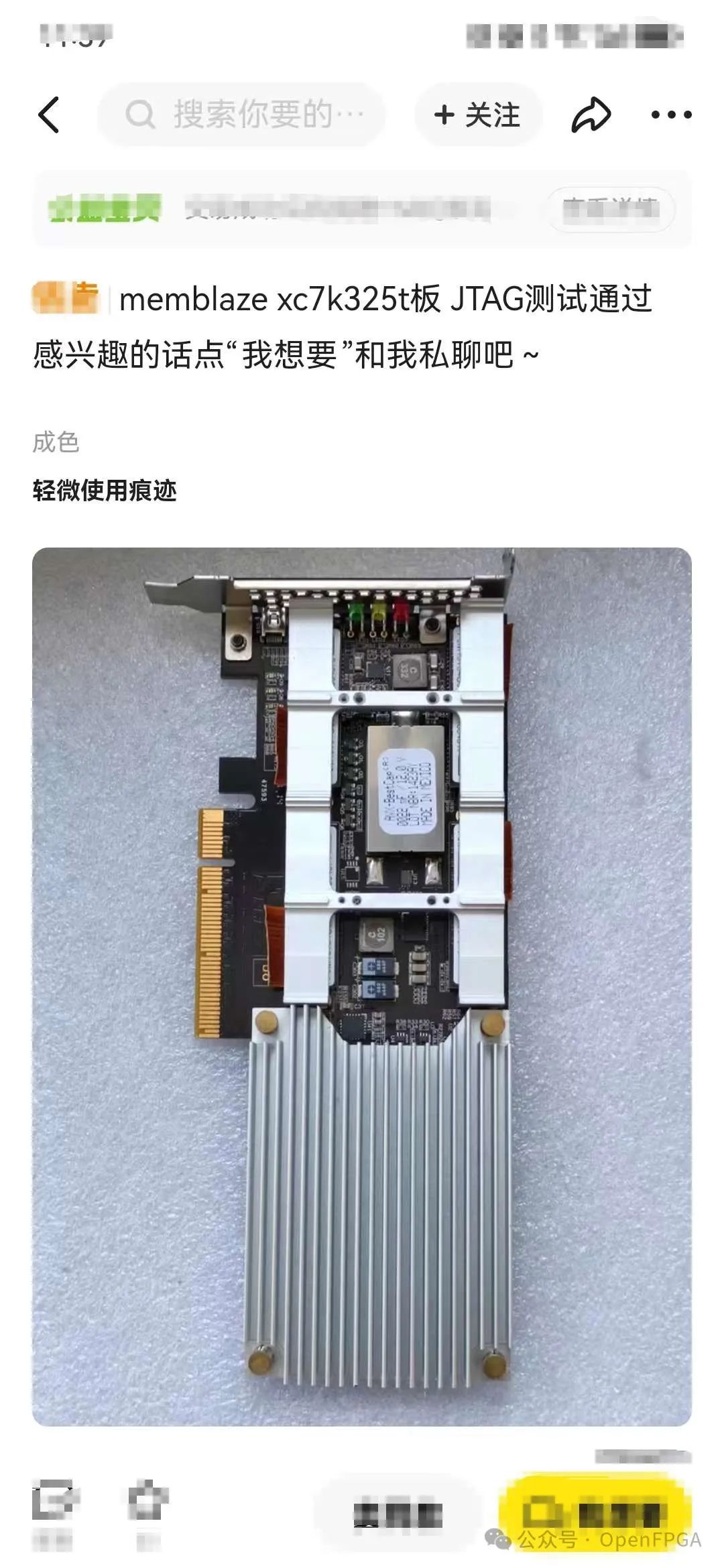
On various second-hand websites, you can often find boards that lack accompanying documentation (such as schematics), and these boards are relatively inexpensive. If purchased in bulk, they can be used as development boards. The first challenge is to “reverse engineer” the schematics for subsequent routine development.
Currently, there are two software tools that can assist with such tasks: XJTAG and TopJTAG (as far as I know). I will use TopJTAG as an example since it has a modified version available.
Principle
The original purpose of JTAG was for chip testing, specifically the Boundary-scan technology. Common standards include IEEE1149.1, IEEE1149.6, and IEEE1532. By using devices compatible with these standards, one can access the internal nodes or I/O of the chip. We will utilize this feature of JTAG to infer the relevant pins using TopJTAG.
Installation
Download the shared file: TopJTAG Probe.zip link: https://pan.baidu.com/s/1WZE9Pkx5HSquyVmAd0BcGA?pwd=u4g7
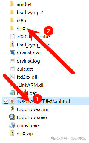
After extracting, open the two exe files shown below:
Follow the steps below to generate the registration code:

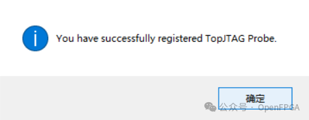
Registration successful:
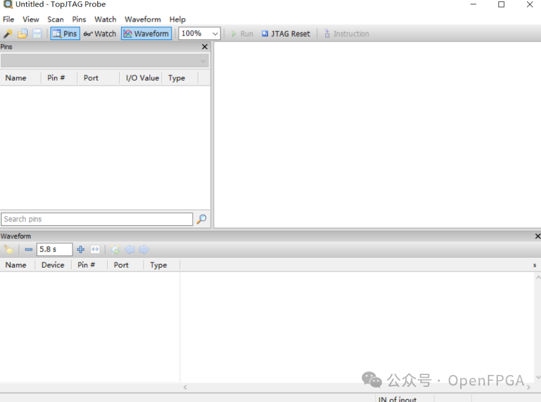
Usage
The software is extremely simple and has a layout similar to conventional EDA software.
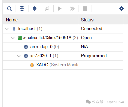
First, use the EDA software from the corresponding chip manufacturer to scan for the chip:
Create a new project in TopJTAG:
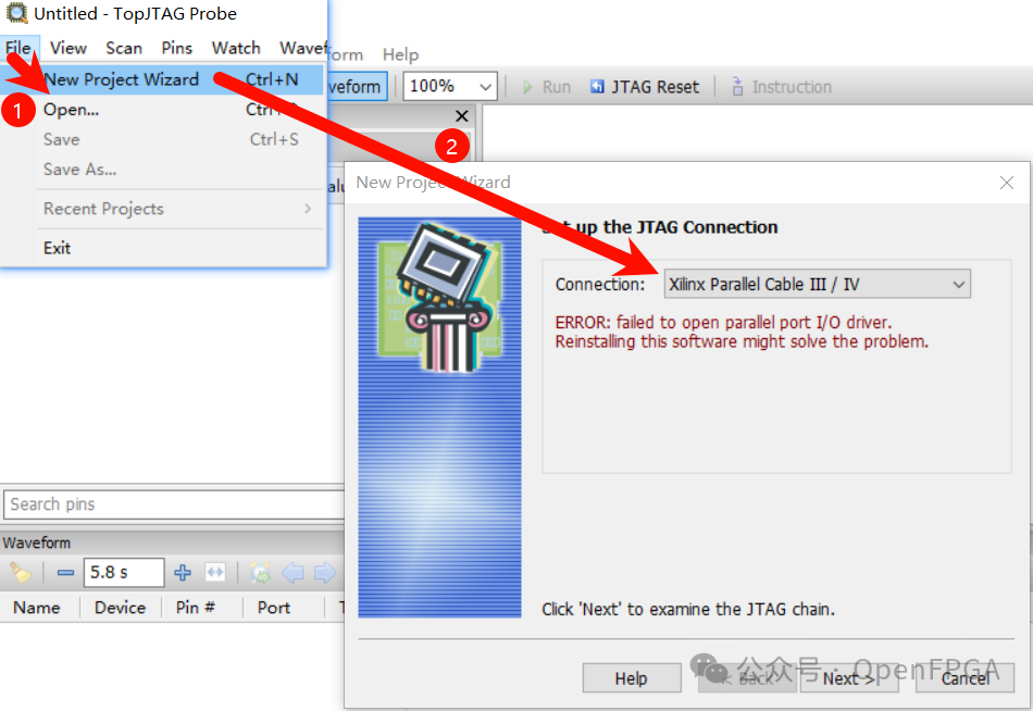
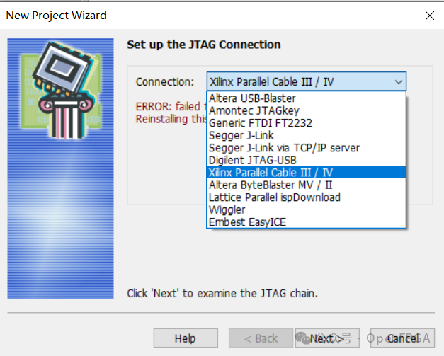
Select the corresponding emulator; Probe supports many mainstream emulators, as shown below:
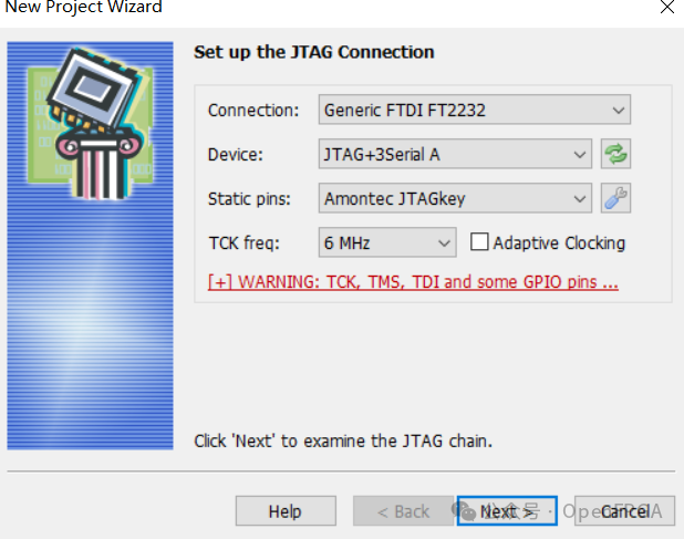
Connect according to the type of JTAG you are using; we will use FT4232 for Xilinx JTAG:
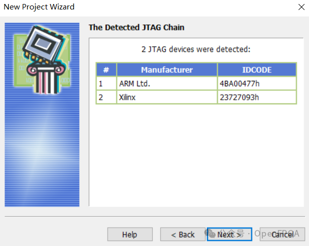
The software will automatically scan the target board’s JTAG chain, displaying the device ID and manufacturer on the chain. Once the chip is detected, you can proceed:
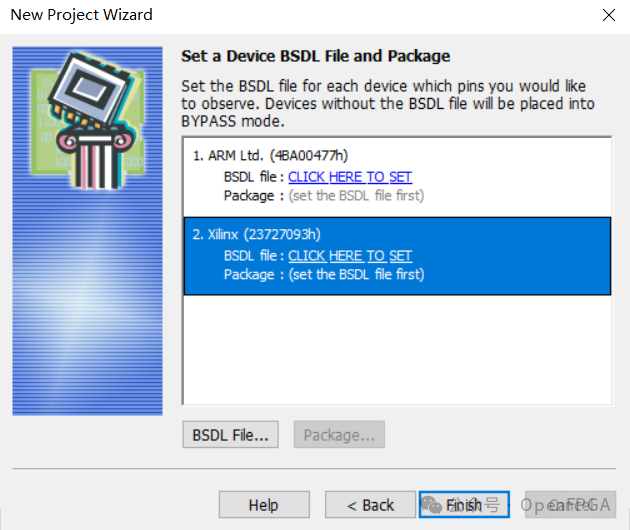
Next is the most crucial step: locate the BSDL file (this file defines device information according to IEEE standards):
The BSDL file can be obtained from the chip manufacturer. For example, the BSDL page for Altera MAX II is:
https://www.altera.com/support/devices/bsdl/11491/bsd-11491.html
The download link for ST’s STM32 series BSDL is:
https://www.st.com/internet/com/SOFTWARE_RESOURCES/HW_MODEL/BSDL_MODEL/stm32bsdl.zip
The download link for Xilinx’s Versal, Zynq UltraScale+, Zynq 7000 SoCs, UltraScale+, UltraScale, and 7 series FPGAs BSDL is:
https://www.xilinx.com/support/download/index.html/content/xilinx/en/downloadNav/device-models.html
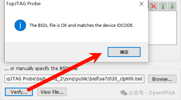
Once the BSDL file is selected and verified, you can continue with the subsequent operations:
The corresponding chip information will be displayed in the window:
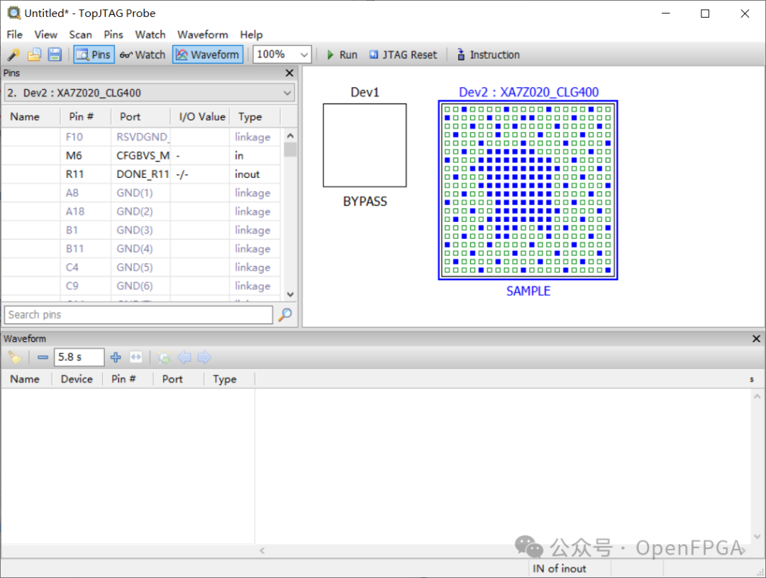
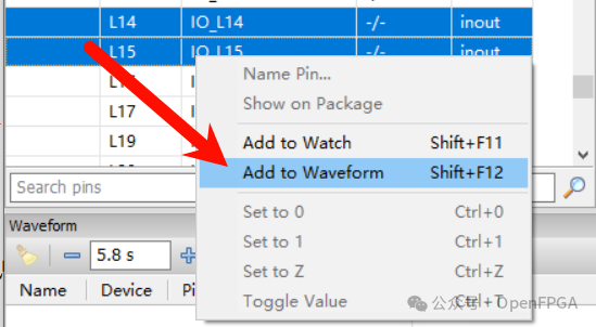
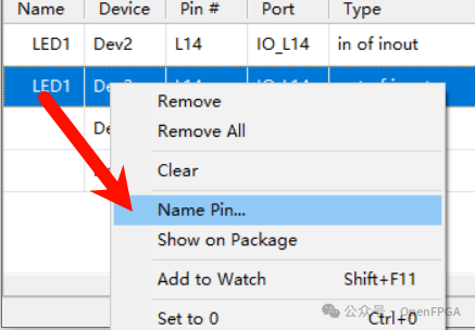
On the left side, there is a pin definition section; right-click to add I/O to the waveform window.
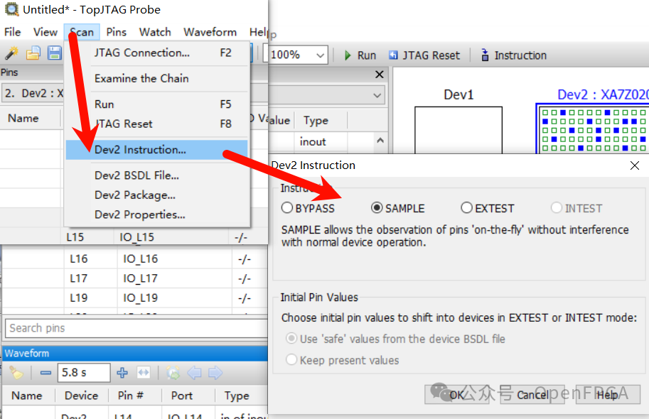
Since we are testing external hardware circuits, click the Instruction button on the toolbar and select EXTEST mode. The SAMPLE mode can monitor the chip’s status without interfering with its normal operation, while the INTEST mode tests the chip’s internal logic. For devices on the JTAG chain that can be ignored, you can select BYPASS.
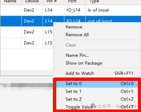
In the waveform window, set the pin output levels to 0, 1, or toggle them.
Click run to see the effect; similarly, you can change the pin states during operation.
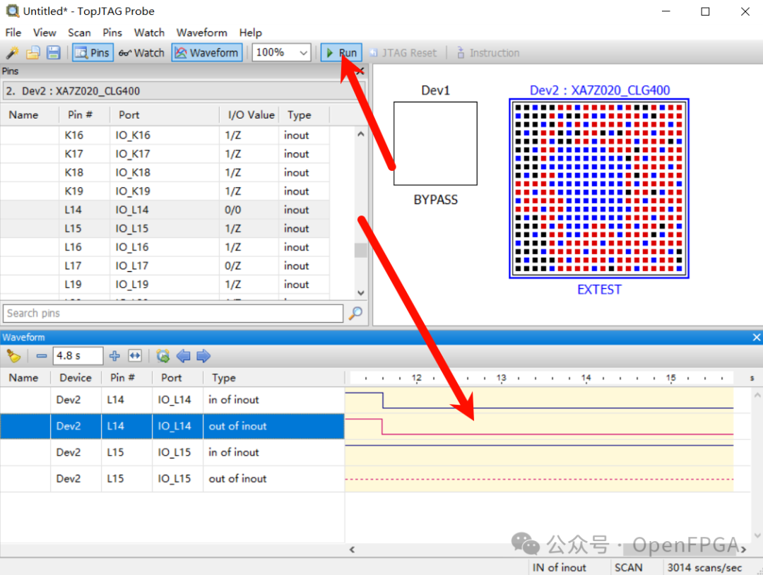
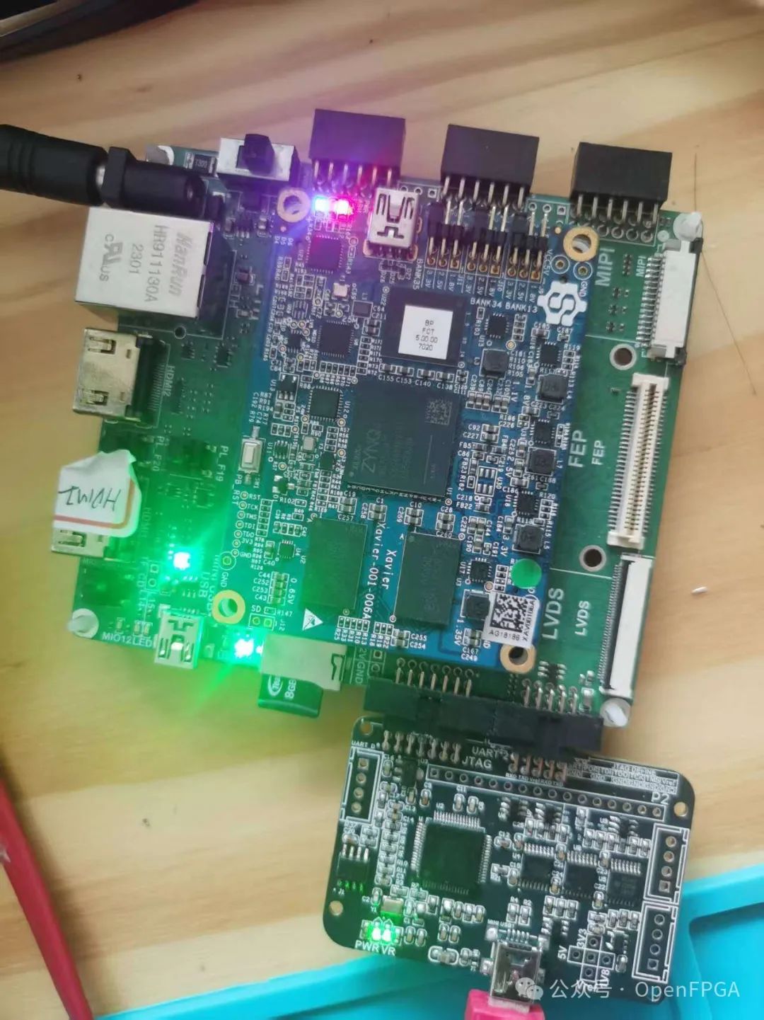
The result is shown in the image below, where several LEDs are lit up using TopJTAG and JTAG:
Conclusion
Currently, I estimate that many people are still unclear about how to perform “reverse engineering”. In fact, it is quite simple: by setting the relevant pins high or low or inputting a low-frequency square wave (some have tested that the Probe’s time resolution is at the millisecond level), you can monitor which pins change state, thus identifying which pin belongs to the chip.
I/O names can be manually set, and if there is a constraint file, it can be imported to automatically obtain I/O names.
This is just one of the less “glamorous” applications of TopJTAG; in fact, it has many applications in troubleshooting both software and hardware, and the rest is up to everyone to explore gradually.
Finally, the current version is not the latest; if anyone has the latest version, please share it in the comments!