19.6
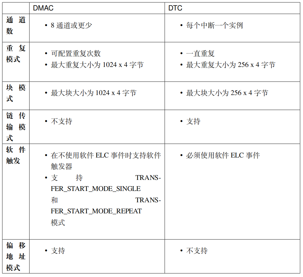
Comparison of Key Features between DMAC and DTC
The transfer APIs in the FSP library can be implemented by either DMAC or DTC, so theoretically, we can switch between DMAC and DTC. However, DMAC and DTC have some differences, so please consider the following factors when choosing between them:
Table 2: Comparison of Features between DMAC and DTC
Interrupts
The interrupt behavior of DTC and DMAC is different:
-
DTC uses the configured IELSR event IRQ as the interrupt source.
-
Each DMAC channel has its own IRQ.
Other Considerations:
-
DTC requires a certain amount of RAM.
-
DTC stores transfer information in RAM and writes back to RAM after each transfer, while DMAC stores all transfer information in registers.
-
When configuring transfers for multiple activation sources, DTC must retrieve transfer information from RAM at each interrupt. This may result in higher delays between transfers.
-
DTC uses the IRQ of the activation source to interrupt the CPU. Each DMAC channel has its own IRQ.
Additionally, the setting of the transfer_info_t::irq attribute for transfer information behaves slightly differently depending on the selected mode.
Table 3: Normal Mode
|
Interrupt Mode |
DMAC |
DTC |
|
TRANSFER_IRQ_EACH |
N/A |
Interrupt after each transfer |
|
TRANSFER_IRQ_END |
Interrupt after completing the last transfer |
Interrupt after completing the last transfer |
Table 4: Repeat Mode
|
Interrupt Mode |
DMAC |
DTC |
|
TRANSFER_IRQ_EACH |
Interrupt after each transfer |
Interrupt after each transfer |
|
TRANSFER_IRQ_END |
Interrupt after completing the last transfer |
Interrupt after each transfer |
Table 5: Block Mode
|
Interrupt Mode |
DMAC |
DTC |
|
TRANSFER_IRQ_EACH |
Interrupt after each transfer |
Interrupt after each transfer |
|
TRANSFER_IRQ_END |
Interrupt after completing the last transfer |
Interrupt after completing the last transfer |
Table 6: Repeat-Block Mode
|
Interrupt Mode |
DMAC |
DTC |
|
TRANSFER_IRQ_EACH |
N/A |
N/A |
|
TRANSFER_IRQ_END |
Interrupt after completing the last transfer |
N/A |
19.7
Experiment 1: Memory-to-Memory Transfer using DMAC
19.7.1
Software Design
19.7.1.1
Create a New Project
Since this experiment requires the use of LEDs and serial port printing for debugging information, we will modify the program based on the “Experiment 1: UART Echo” example from the previous chapter.
-
For e2 studio development environment: Copy our previous e2s project “19_UART_Receive_Send“, then rename the project folder to “20_DMAC_Memory_To_Memory“, and finally import it into our e2 studio workspace.
-
For Keil development environment: Copy our previous Keil project “19_UART_Receive_Send“, then rename the project folder to “20_DMAC_Memory_To_Memory“, and double-click the Keil project file inside that folder to open the project.
After creating the project, create a new folder named “dmac” under the “src” folder in the project root directory, and then create the source file and header file inside the “dmac” folder: “bsp_dmac_m2m.c” and “bsp_dmac_m2m.h”. The project file structure is as follows.
List 1: File Structure
Swipe left and right to view the full content
20_DMAC_Memory_To_Memory├─ ......└─ src├─ led│ │ ├─ bsp_led.c│ └─ bsp_led.h├─ debug_uart│ ├─ bsp_debug_uart.c│ └─ bsp_debug_uart.h├─ dmac│ ├─ bsp_dmac_m2m.c│ └─ bsp_dmac_m2m.h└─ hal_entry.c19.7.1.2
FSP Configuration
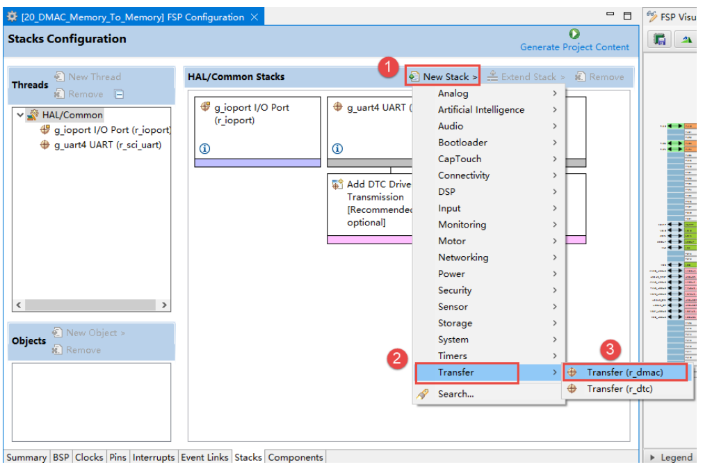
Open the FSP configuration interface for this project. Then follow the steps in the figure to add DMAC.
After adding DMAC, it will look like the following image.
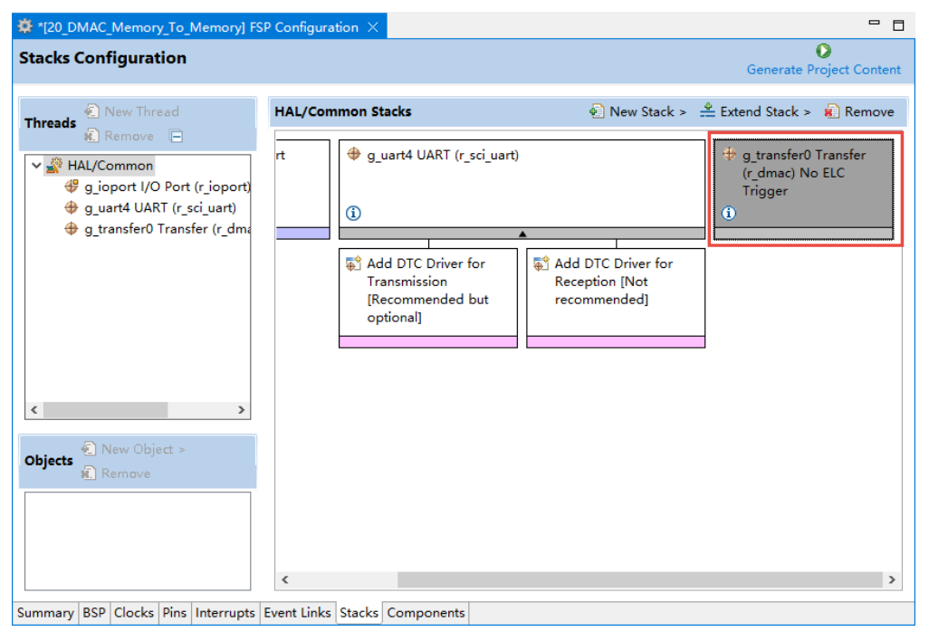
We click on the newly added r_dmac box in the image above, and then configure the various attribute parameters of the DMAC module in the “Properties” window at the bottom left. Configure as shown in the following image.
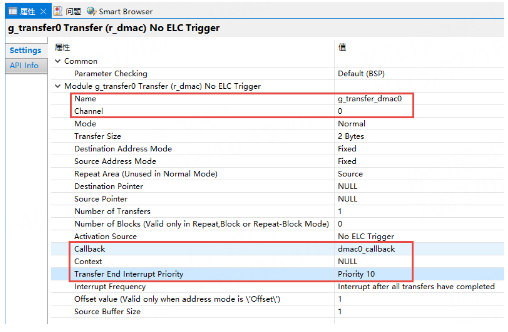
In the image above, you only need to configure the attributes in the box; the other attributes can remain at their defaults.
DMAC configuration items (corresponding to the above image):
Table 7: Description of DMAC Configuration Attributes
|
Attribute |
Description |
|
Name |
Name. The configuration in the above image is g_transfer_dmac0, set according to your naming convention, and ensure it corresponds with the code. |
|
Channel |
Channel: DMA transfer channel selection. Here, select channel 0, which is also the highest priority channel. RA6M5 has 8 channels, 0~7 selectable. Other MCU models may differ. |
|
Mode |
Mode: DMA transfer mode selection. The default is to select normal mode. |
|
Transfer Size |
Transfer Size: The size of the data unit to be transferred. The default is set to 2 bytes. |
|
Destination Address Mode |
Destination Address Mode: The default is set to fixed. |
|
Source Address Mode |
Source Address Mode: The default is set to fixed. |
|
Repeat Area (Unused in Normal Mode) |
Repeat Area (not used in Normal Mode): Source address. |
|
Destination Pointer |
Destination Pointer: NULL (the transfer address cannot be determined here, it will be configured in the code section later). |
|
Source Pointer |
Source Pointer: NULL (the transfer address cannot be determined here, it will be configured in the code section later). |
|
Number of Transfers |
Number of Transfers: Specifies the number of transfers in normal and repeat modes or the block size in repeat-block transfer mode. |
|
Number of Blocks (Valid only in Repeat, Block or Repeat-Block Mode) |
Number of Blocks: Specifies the number of blocks to be transferred in repeat, block, or repeat-block mode. |
|
Activation Source |
Activation Source: Select the event that starts the DMAC transfer. If no ELC event is selected, software can be used to start. |
|
Callback |
Callback Function: The callback function called when the DMAC interrupt is triggered. This is set to dmac0_callback. |
|
Context |
Context: A pointer to the context structure passed through the callback function. |
|
Transfer End Interrupt Priority |
Transfer End Interrupt Priority: The priority setting for the transfer end interrupt. |
After configuration is complete, click to generate code, and then we can start writing our code.

Need Technical Support?
If you have any questions while using Renesas MCU/MPU products, you can scan the QR code below or copy the URL into your browser to access the Renesas Technical Forum for answers or to get online technical support.

https://community-ja.renesas.com/zh/forums-groups/mcu-mpu/
To be continued
Recommended Reading
DMAC/DTC: Direct Memory Access and Data Transfer – Practical Guide to Developing with Renesas RA Series FSP Library (51)
Analysis of DMAC Module Block Diagram – Practical Guide to Developing with Renesas RA Series FSP Library (52)
Analysis of DTC Module Block Diagram – Practical Guide to Developing with Renesas RA Series FSP Library (53)